
R3303-HP HSR6800 Routers MPLS Configuration Guide

190
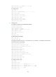
0.00% packet loss
round-trip min/avg/max = 30/50/70 ms
Example for configuring Martini VC redundancy
Network requirements
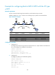
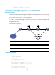
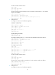
The CEs are connected to the PEs through serial interfaces and PPP encapsulation is used at the link layer.
Create two Martini VCs between CE 1 and CE 2, one is CE 1 – PE 1 – PE 2 – CE 2 (the primary VC) and
the other is CE 1 – PE 1 – PE 3 – CE 2 (the backup VC).
CE 1 and CE 2 communicate through the primary VC when this VC is working correctly. When PE 1
detects that the primary VC fails, it brings up the backup VC so that CE 1 and CE 2 can communicate
through the backup VC.
Figure 49 Network diagram
Device Interface IP address
Device
Interface
IP address
CE 1 S2/1/0 100.1.1.1/24 PE 2 Loop0 2.2.2.2/32
S2
/
1
/
0 100.2.1.1/24 sub
S2
/
1
/
0
12.1.1.2/24
S2
/
1
/
1 100.3.1.1/24
PE 3
Loop0
3.3.3.3/32
PE 1 Loop0 1.1.1.1/32 S2/1/0 13.1.1.3/24
S2
/
1
/
1 12.1.1.1/24
CE 2
S2
/
1
/
0
100.1.1.2/24
S2
/
1
/
2 13.1.1.1/24
S2
/
1
/
1
100.2.1.2/24
Configuration procedure
1. Configure CE 1:
# Assign IP address to interfaces.
<Sysname> system-view
[Sysname] sysname CE1
[CE1] interface serial 2/1/0
[CE1-Serial2/1/0] link-protocol ppp
[CE1-Serial2/1/0] ip address 100.1.1.1 24
[CE1-Serial2/1/0] ip address 100.2.1.1 24 sub
[CE1-Serial2/1/0] quit
[CE1] interface serial 2/1/1
[CE1-Serial2/1/1] link-protocol ppp