
R3303-HP HSR6800 Routers MPLS Configuration Guide

201
Example for configuring a VC for a service instance
This configuration example applies only to routers with SAP-4EXPs.
Network requirements
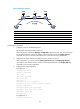
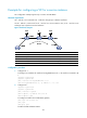
CE 1 and CE 2 are connected to PE 1 and PE 2 through Layer 3 Ethernet interfaces.
On PE 1 and PE 2, create a VC for CE 1 and CE 2 in service instance view, so CE 1 and CE 2 can
exchange Layer 2 packet across the backbone.
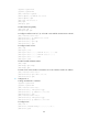
Figure 52 Network diagram
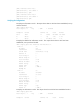
Device Interface IP address
Device
Interface
IP address
CE 1 XGE1/0/1 100.1.1.1/24 P Loop0 192.4.4.4/32
PE 1 Loop0 192.2.2.2/32
XGE1/0/2 23.1.1.2/24
XGE1/0/2 23.1.1.1/24
XGE1/0/3 26.2.2.2/24
CE 2 XGE1/0/1 100.1.1.2/32 PE 2 Loop0 192.3.3.3/32
XGE1/0/3 26.2.2.1/24
Configuration procedure
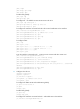
1. Configure CE 1:
# Configure an IP address for interface Ten-GigabitEthernet1/0/1, the interface connected to PE
1.
<Sysname> system-view
[Sysname] sysname CE1
[CE1] interface ten-GigabitEthernet 1/0/1
[CE1-Ten-GigabitEthernet1/0/1] ip address 100.1.1.1 24
2. Configure PE 1:
<Sysname> system-view
[Sysname] sysname PE1
[PE1] interface loopback 0
[PE1-LoopBack0] ip address 192.2.2.2 32
[PE1-LoopBack0] quit
# Configure the LSR ID and enable MPLS globally.
[PE1] mpls lsr-id 192.2.2.2
[PE1] mpls
[PE1-mpls] quit
# Enable L2VPN and MPLS L2VPN.