
R3303-HP HSR6800 Routers MPLS Configuration Guide

226
[PE2-Ten-GigabitEthernet1/0/1] port trunk permit vlan 100 200
[PE2-Ten-GigabitEthernet1/0/1] service-instance 1
[PE2-Ten-GigabitEthernet1/0/1-srv1] encapsulation s-vid 100
[PE2-Ten-GigabitEthernet1/0/1-srv1] xconnect vsi aaa
[PE2-Ten-GigabitEthernet1/0/1-srv1] quit
[PE2-Ten-GigabitEthernet1/0/1] service-instance 2
[PE2-Ten-GigabitEthernet1/0/1-srv2] encapsulation s-vid 200
[PE2-Ten-GigabitEthernet1/0/1-srv2] xconnect vsi bbb
[PE2-Ten-GigabitEthernet1/0/1-srv2] quit
Verifying the configuration:
# Execute the display vpls connection command on the PEs. The output shows that a PW
connection in up state has been established. Take PE 2 as an example:
[PE2] display vpls connection vsi aaa verbose
VSI Name: aaa Signaling: ldp
**Remote Vsi ID : 500
VC State : up
Encapsulation : vlan
Group ID : 0
Remote MTU : 1500
Peer Ip Address : 1.1.1.9
PW Type : label
Local VC Label : 89766
Remote VC Label : 81922
Link ID : 1
Tunnel Policy : --
Tunnel ID : 0x4600068
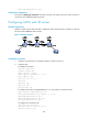
Configuring VPLS instances
Network requirements
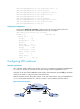
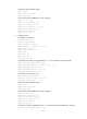
CE 1 and CE 2 reside in different sites of VPN 1. Each CE is connected to the interface GigabitEthernet
2/1/2 of a PE. The PEs are connected to each other through interface GigabitEthernet 2/1/1.
Configure an LDP VPLS instance aaa (the Martini mode), and a BGP VPLS instance bbb (the Kompella
mode, the AS number is 100), and a static VPLS instance ccc.
Bind the LDP VPLS instance, BGP VPLS instance, or the static VPLS instance with port GigabitEthernet
2/1/2, so that packets between CE 1 and CE 2 in VPN 1 are forwarded by the VPLS instance.
Figure 60 Network diagram