
R3303-HP HSR6800 Routers MPLS Configuration Guide

230
[PE2-GigabitEthernet2/1/2] quit
Verifying the configuration:
# Execute the display vpls connection command on the PEs. The output shows that a PW connection in
up state has been established between the PEs.
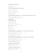
Configuring H-VPLS with LSP access
Network requirements
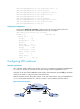
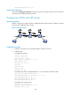
Establish a U-PW between UPE and NPE 1. Establish an N-PW between NPE 1 and NPE 3. Create an
LDP VPLS instance aaa (the Martini mode).
Figure 61 Network diagram
Configuration procedure
1. Configure an IGP protocol on the MPLS backbone. (Details not shown.)
2. Configure UPE:
# Configure basic MPLS.
<Sysname> system-view
[Sysname] sysname UPE
[UPE] interface loopback 0
[UPE-LoopBack0] ip address 1.1.1.9 32
[UPE-LoopBack0] quit
[UPE] mpls lsr-id 1.1.1.9
[UPE] mpls
[UPE-mpls] quit
[UPE] mpls ldp
[UPE-mpls-ldp] quit
# Configure basic MPLS on GigabitEthernet 2/1/2, the interface connected to NPE 1.
[UPE] interface gigabitethernet 2/1/2
[UPE-GigabitEthernet2/1/2] ip address 10.1.1.1 24
[UPE-GigabitEthernet2/1/2] mpls
[UPE-GigabitEthernet2/1/2] mpls ldp
[UPE-GigabitEthernet2/1/2] quit
# Configure the remote LDP peer.
[UPE] mpls ldp remote-peer 1
[UPE-mpls-remote-1] remote-ip 2.2.2.9
[UPE-mpls-remote-1] quit