
R3303-HP HSR6800 Routers MPLS Configuration Guide

233
[NPE3-GigabitEthernet2/1/1] l2 binding vsi aaa
[NPE3-GigabitEthernet2/1/1] quit
Verifying the configuration:
# Execute the display vpls connection command on the PEs. The output shows that a PW connection in
up state has been established between the PEs.
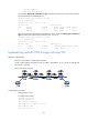
Configuring PW redundancy for H-VPLS access
Network requirements
CE 1 and CE 2 are connected to the UPE through an Ethernet.
Establish a U-PW between UPE and NPE 1 and a backup U-PW between UPE and NPE 2. Establish an
N-PW between NPE 1 and NPE 3 and another N-PW between NPE 2 and NPE 3. Configure a VPLS
instance that supports H-VPLS network.
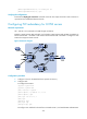
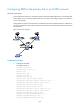
Figure 62 Network diagram
Configuration procedure
1. Configure an IGP on the MPLS backbone. (Details not shown.)
2. Configure UPE:
# Configure basic MPLS.
<Sysname> system-view
[Sysname] sysname UPE
[UPE] interface loopback 0
[UPE-LoopBack0] ip address 1.1.1.1 32
[UPE-LoopBack0] quit
[UPE] mpls lsr-id 1.1.1.1
[UPE] mpls
[UPE-mpls] quit
[UPE] mpls ldp
[UPE-mpls-ldp] quit
# Configure an IP address for the interface connected to NPE 1, and enable MPLS and MPLS LDP.