
R3303-HP HSR6800 Routers MPLS Configuration Guide


265
OSPF for VPNs on a PE
OSPF is a prevalent IGP protocol. It often runs between a PE and a CE to simplify CE configuration and
management because the CEs only need to support OSPF. In addition, if the customers require MPLS
L3VPN services through conventional OSPF backbone, using OSPF between a PE and a CE can simplify
the transition.
For OSPF to run between CE and PE, the PE must support multiple OSPF processes. Each OSPF process
must correspond to a VPN instance and have its own interface and routing table.
Details of OSPF configuration between a PE and a CE are described here.
• Configuration of OSPF areas between a PE and a CE
The OSPF area between a PE and a CE can be either a non-backbone area or a backbone area.
In the OSPF VPN extension application, the MPLS VPN backbone is considered the backbone area
(area 0). The area 0 of each VPN site must be connected to the MPLS VPN backbone because
OSPF requires that the backbone area be contiguous.
If a VPN site contains an OSPF area 0, the connected PE must be connected to the backbone area
of the VPN site through area 0. You can configure a logical connection by using a virtual link.
• BGP/OSPF interaction
PEs advertise VPN routes to each other through BGP and to CEs through OSPF.
Conventional OSPF considers two sites to be in different ASs even if they belong to the same VPN.
Therefore, the routes that one site learns are advertised to the other as external routes. This results
in more OSPF traffic and network management problems.
The extended OSPF protocol supports multiple instances to address the previous problems.
Properly configured, OSPF sites are considered directly connected, and PEs can exchange OSPF
routing information as they are using dedicated lines. This improves network management and
makes OSPF applications more effective.
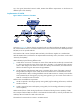
As shown in
Figure 80, PE 1 and PE
2 are connected through the MPLS backbone. CE 11, CE 21,
and CE 22 belong to VPN 1. Assume that CE 11, CE 21, and CE 22 belong to the same OSPF
domain. PEs advertise VPN 1 routes in the following procedure:
a. PE 1 redistributes OSPF routes from CE 11 into BGP.
b. PE 1 advertises the VPN routes to PE 2 through BGP.
c. PE 2 redistributes the BGP VPN routes into OSPF and advertises them to CE 21 and CE 22.
Figure 80 Application of OSPF in VPN