
R3303-HP HSR6800 Routers MPLS Configuration Guide

269
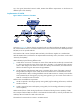
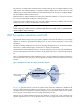
Configure echo-mode BFD on PE 2 to detect the link from PE 2 to CE 2. When the link is available, traffic
from CE 1 to CE 2 takes the path CE 1—PE 1—PE 2—CE 2. When the link fails, PE 2 switches fast to the
link PE 2—PE 3—CE 2, and traffic from CE 1 to CE 2 takes the path CE 1—PE 1—PE 2—PE 3—CE 2.
This avoids traffic forwarding interruption before route convergence (switching back to the link CE 1—PE
1—PE 3—CE 2).
In this scenario, PE 2 is responsible for primary link detection and traffic switchover.
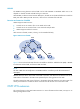
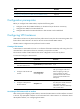
Multi-VPN-instance CE
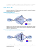
BGP/MPLS VPN transmits private network data through MPLS tunnels over the public network. However,
the traditional MPLS L3VPN architecture requires that each VPN instance use an exclusive CE to connect
to a PE, as shown in Figure 65.
F
or better services and higher security, a private network is usually divided into multiple VPNs to isolate
services. To meet these requirements, you can configure a CE for each VPN, which increases device
expense and maintenance costs. Or, you can configure multiple VPNs to use the same CE and the same
routing table, which sacrifices data security.
Using the Multi-VPN-Instance CE (MCE) function, you can remove the contradiction of low cost and high
security in multi-VPN networks. MCE allows you to bind each VPN to a VLAN interface. The MCE creates
and maintains a separate routing table for each VPN. This separates the forwarding paths of packets of
different VPNs and, in conjunction with the PE, can correctly advertise the routes of each VPN to the peer
PE, ensuring the normal transmission of VPN packets over the public network.
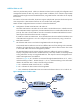
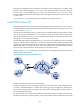
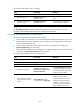
The following uses Figure 85 t
o describe how an MCE maintains the routing tables for multiple VPNs and
exchanges VPN routes with PEs.
Figure 85 Network diagram for the MCE function
Establish a tunnel between the two sites of each VPN.
Create a routing table for VPN 1 and VPN 2, respectively, on the MCE device, and bind VLAN-interface
2 to VPN 1 and VLAN-interface 3 to VPN 2. When receiving a route, the MCE device determines the
source of the routing information according to the number of the receiving interface, and then adds it to
the corresponding routing table.
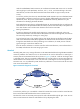
You must also bind PE 1's interfaces/subinterfaces connected to the MCE to the VPNs in the same way.
The MCE connects to PE 1 through a trunk link, which permits packets of VLAN 2 and VLAN 3 with VLAN