
R3303-HP HSR6800 Routers MPLS Configuration Guide
307
[P-LoopBack0] ip address 2.2.2.9 32
[P-LoopBack0] quit
[P] interface pos 5/1/1
[P-POS5/1/1] ip address 172.1.1.2 24
[P-POS5/1/1] quit
[P] interface pos 5/1/2
[P-POS5/1/2] ip address 172.2.1.1 24
[P-POS5/1/2] quit
[P] ospf
[P-ospf-1] area 0
[P-ospf-1-area-0.0.0.0] network 172.1.1.0 0.0.0.255
[P-ospf-1-area-0.0.0.0] network 172.2.1.0 0.0.0.255
[P-ospf-1-area-0.0.0.0] network 2.2.2.9 0.0.0.0
[P-ospf-1-area-0.0.0.0] quit
[P-ospf-1] quit
# Configure PE 2.
<PE2> system-view
[PE2] interface loopback 0
[PE2-LoopBack0] ip address 3.3.3.9 32
[PE2-LoopBack0] quit
[PE2] interface pos 5/1/1
[PE2-POS5/1/1] ip address 172.2.1.2 24
[PE2-POS5/1/1] quit
[PE2] ospf
[PE2-ospf-1] area 0
[PE2-ospf-1-area-0.0.0.0] network 172.2.1.0 0.0.0.255
[PE2-ospf-1-area-0.0.0.0] network 3.3.3.9 0.0.0.0
[PE2-ospf-1-area-0.0.0.0] quit
[PE2-ospf-1] quit
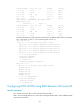
After the configurations, OSPF adjacencies are established between PE 1, P, and PE 2. Execute the
display ospf peer command. The output shows that the adjacency status is Full. Execute the display
ip routing-table command. The output shows that the PEs have learned the routes to the loopback
interfaces of each other. Take PE 1 as an example:
[PE1] display ip routing-table
Routing Tables: Public
Destinations : 8 Routes : 8
Destination/Mask Proto Pre Cost NextHop Interface
1.1.1.9/32 Direct 0 0 127.0.0.1 InLoop0
2.2.2.9/32 OSPF 10 1 172.1.1.2 POS5/1/1
3.3.3.9/32 OSPF 10 2 172.1.1.2 POS5/1/1
127.0.0.0/8 Direct 0 0 127.0.0.1 InLoop0
127.0.0.1/32 Direct 0 0 127.0.0.1 InLoop0
172.1.1.0/24 Direct 0 0 172.1.1.1 POS5/1/1
172.1.1.1/32 Direct 0 0 127.0.0.1 InLoop0
172.2.1.0/24 OSPF 10 1 172.1.1.2 POS5/1/1
[PE1] display ospf peer verbose
OSPF Process 1 with Router ID 1.1.1.9
Neighbors