
R3303-HP HSR6800 Routers MPLS Configuration Guide
319
[PE2] route-policy pe-ibgp permit node 0
[PE2-route-policy] apply ip-address next-hop 1.1.1.9
[PE2-route-policy] quit
[PE2] bgp 100
[PE2-bgp] peer 1.1.1.9 as-number 100
[PE2-bgp] peer 1.1.1.9 connect-interface loopback 0
[PE2-bgp] ipv4-family vpnv4
[PE2-bgp-af-vpnv4] peer 1.1.1.9 route-policy pe-ibgp import
[PE2-bgp-af-vpnv4] peer 1.1.1.9 enable
[PE2-bgp-af-vpnv4] quit
[PE2-bgp] quit
Execute the display bgp peer command or the display bgp vpnv4 all peer command on the PEs.
The output shows that a BGP peer relationship has been established between the PEs, and has
reached the Established state. Take PE 1 as an example.
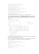
[PE1] display bgp peer
BGP local router ID : 1.1.1.9
Local AS number : 100
Total number of peers : 1 Peers in established state : 1
Peer AS MsgRcvd MsgSent OutQ PrefRcv Up/Down State
3.3.3.9 100 2 6 0 0 00:00:12 Established
6. Verify the configuration:
# Execute the display ip routing-table vpn-instance command on the PEs. The output shows the
routes to the peer CEs. Take PE 1 as an example:
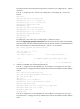
[PE1] display ip routing-table vpn-instance vpn1
Routing Tables: vpn1
Destinations : 7 Routes : 7
Destination/Mask Proto Pre Cost NextHop Interface
4.4.4.9/32 BGP 255 0 10.1.1.1 GE2/1/1
6.6.6.9/32 BGP 255 0 3.3.3.9 NULL0
10.1.1.0/24 Direct 0 0 10.1.1.2 GE2/1/1
10.1.1.2/32 Direct 0 0 127.0.0.1 InLoop0
10.3.1.0/24 BGP 255 0 3.3.3.9 NULL0
127.0.0.0/8 Direct 0 0 127.0.0.1 InLoop0
127.0.0.1/32 Direct 0 0 127.0.0.1 InLoop0
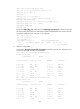
[PE1] display ip routing-table vpn-instance vpn2
Routing Tables: vpn2
Destinations : 7 Routes : 7
Destination/Mask Proto Pre Cost NextHop Interface
5.5.5.9/32 BGP 255 0 10.2.1.1 GE2/1/2
7.7.7.9/32 BGP 255 0 3.3.3.9 NULL0
10.2.1.0/24 Direct 0 0 10.2.1.2 GE2/1/2
10.2.1.2/32 Direct 0 0 127.0.0.1 InLoop0
10.4.1.0/24 BGP 255 0 3.3.3.9 NULL0
127.0.0.0/8 Direct 0 0 127.0.0.1 InLoop0