
R3303-HP HSR6800 Routers MPLS Configuration Guide

321
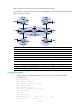
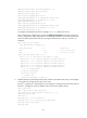
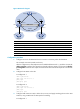
Figure 88 Network diagram
Device Interface IP address
Device
Interface
IP address
CE 1 GE2/1/1 10.1.1.1/24 P POS5/1/1 172.1.1.2/24
PE 1 Loop0 1.1.1.9/32
POS5/1/2 172.2.1.1/24
GE2/1
/
1 10.1.1.2/24
PE 2
Loop0
2.2.2.9/32
POS5/1/2 172.1.1.1/24 GE2/1/1 10.2.1.2/24
Tunnel0 20.1.1.1/24
POS5/1/1 172.2.1.2/24
CE 2 GE2/1
/
1 10.2.1.1/24
Tunnel0
20.1.1.2/24
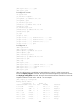
Configuration procedure
1. Configure an IGP on the MPLS backbone to ensure IP connectivity within the backbone:
This example uses OSPF. (Details not shown.)
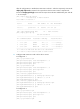
After the configurations, OSPF adjacencies are established between PE 1, P, and PE 2. Execute the
display ospf peer command. The output shows that the adjacency status is Full. Execute the display
ip routing-table command. The output shows that the PEs have learned the loopback route of each
other.
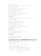
2. Configure basic MPLS on the PEs:
# Configure PE 1.
<PE1> system-view
[PE1] mpls lsr-id 1.1.1.9
[PE1] mpls
[PE1-mpls] quit
# Configure PE 2.
<PE2> system-view
[PE2] mpls lsr-id 2.2.2.9
[PE2] mpls
[PE2-mpls] quit
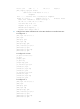
3. Configure VPN instances on PEs to allow CEs to access, and apply tunneling policies to the VPN
instances, using a GRE tunnel for VPN packet forwarding:
# Configure PE 1.
Loop0 Loop0
POS5/1/1 POS5/1/2
POS5/1/1POS5/1/1
Tunnel0
Tunnel0
GE2/1/1GE2/1/1
GE2/1/1 GE2/1/1
CE 1
CE 2
VPN 1
VPN 1
AS 65410 AS 65420
PE 1
PE 2
P
AS 100
GRE tunnel