
R3303-HP HSR6800 Routers MPLS Configuration Guide

334
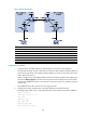
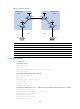
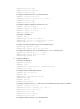
Figure 90 Network diagram
Device Interface IP address
Device
Interface IP address
CE 1 GE2/1/1 10.1.1.1/24 CE 2 GE2/1/1 10.2.1.1/24
PE 1 Loop0 1.1.1.9/32
PE 2
Loop0 4.4.4.9/32
GE2/1
/
1 10.1.1.2/24
GE2/1
/
1 10.2.1.2/24
POS5/1/1 172.1.1.2/24 POS5/1/1 162.1.1.2/24
A
SBR-PE 1 Loop0 2.2.2.9/32
A
SBR-PE 2
Loop0 3.3.3.9/32
POS5/1/1 172.1.1.1/24
POS5/1/1 162.1.1.1/24
POS5/1/2 192.1.1.1/24 POS5/1/2 192.1.1.2/24
Configuration procedure
1. Configure IGP on the MPLS backbone, implementing the connectivity in the backbone:
This example uses OSPF. Be sure to advertise the route to the 32-bit loopback interface address of
each router through OSPF. The loopback interface address of a router is to be used as the router's
LSR ID. (Details not shown.)
After the configurations, each ASBR PE and the PE in the same AS can establish OSPF adjacencies.
Execute the display ospf peer command. The output shows that the adjacencies reach Full state,
and that each ASBR PE and the PE in the same AS can learn the routes to the loopback interfaces
of each other.
Each ASBR PE and the PE in the same AS can ping each other.
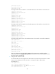
2. Configure basic MPLS and MPLS LDP on the MPLS backbone to establish LDP LSPs:
# Configure basic MPLS on PE 1 and enable MPLS LDP on the interface connected to ASBR PE 1.
<PE1> system-view
[PE1] mpls lsr-id 1.1.1.9
[PE1] mpls
[PE1-mpls] quit
[PE1] mpls ldp
[PE1-mpls-ldp] quit
[PE1] interface pos 5/1/1