
R3303-HP HSR6800 Routers MPLS Configuration Guide

339
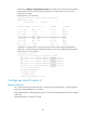
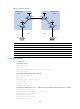
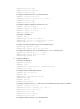
Figure 91 Network diagram
Device Interface IP address
Device
Interface IP address
PE 1 Loop0 2.2.2.9/32 PE 2 Loop0 5.5.5.9/32
GE2/1
/
1 30.0.0.1/8
GE2/1
/
1 20.0.0.1/8
S2/1/1 1.1.1.2/8
S2/1/1 9.1.1.2/8
ASBR-PE 1 Loop0 3.3.3.9/32 ASBR-PE 2 Loop0 4.4.4.9/32
S2/1/1 1.1.1.1/8
S2/1/1 9.1.1.1/8
S2/1/2 11.0.0.2/8
S2/1/2 11.0.0.1/8
Configuration procedure
1. Configure PE 1:
# Start IS-IS on PE 1.
<PE1> system-view
[PE1] isis 1
[PE1-isis-1] network-entity 10.1111.1111.1111.1111.00
[PE1-isis-1] quit
# Configure LSR ID, enable MPLS and LDP.
[PE1] mpls lsr-id 2.2.2.9
[PE1] mpls
[PE1-mpls] label advertise non-null
[PE1-mpls] quit
[PE1] mpls ldp
[PE1-mpls-ldp] quit
# Configure interface Serial 2/1/1, and start IS-IS and enable MPLS and LDP on the interface.
[PE1] interface serial 2/1/1
[PE1-Serial2/1/1] ip address 1.1.1.2 255.0.0.0
[PE1-Serial2/1/1] isis enable 1
[PE1-Serial2/1/1] mpls
[PE1-Serial2/1/1] mpls ldp
[PE1-Serial2/1/1] quit
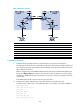
Loop0 Loop0
Loop0 Loop0
S2/1/2
S2/1/1
GE2/1/1
GE2/1/1
CE 1 CE 2
AS 65001 AS 65002
PE 1
PE 2
ASBR-PE 2
ASBR-PE 1
MPLS backbone
MPLS backbone
AS 100
AS 600
Site 1
Site 2
S2/1/1
S2/1/1
S2/1/1
S2/1/2