
R3303-HP HSR6800 Routers MPLS Configuration Guide

374
[SPE2-bgp] peer 2.2.2.9 connect-interface loopback 0
[SPE2-bgp] ipv4-family vpnv4
[SPE2-bgp-af-vpnv4] peer 2.2.2.9 enable
[SPE2-bgp-af-vpnv4] peer 4.4.4.9 enable
[SPE2-bgp-af-vpnv4] peer 4.4.4.9 upe
[SPE2-bgp-af-vpnv4] quit
[SPE2-bgp]ipv4-family vpn-instance vpn1
[SPE2-bgp-vpn1] quit
[SPE2-bgp]ipv4-family vpn-instance vpn2
[SPE2-bgp-vpn2] quit
[SPE2-bgp] quit
# Configure SPE 2 to advertise to UPE 2 the routes permitted by a routing policy, that is, the routes
of CE 1.
[SPE2] ip ip-prefix hope index 10 permit 10.2.1.1 24
[SPE2] route-policy hope permit node 0
[SPE2-route-policy] if-match ip-prefix hope
[SPE2-route-policy] quit
[SPE2] bgp 100
[SPE2-bgp] ipv4-family vpnv4
[SPE2-bgp-af-vpnv4] peer 4.4.4.9 upe route-policy hope export
Configuring OSPF sham links
Network requirements
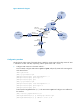
CE 1 and CE 2 belong to VPN 1 and are connected to PE 1 and PE 2, respectively.
CE 1 and CE 2 are in the same OSPF area.
VPN traffic between CE 1 and CE 2 is required to be forwarded through the MPLS backbone, instead of
any route in the OSPF area.
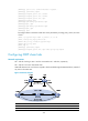
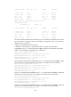
Figure 97 Network diagram
Device Interface IP address Device Interface IP address
CE 1 GE2/1
/
1 100.1.1.1/24
CE 2
GE2/1
/
1 120.1.1.1/24
S2/1/2 20.1.1.1/24
S2/1/2
30.1.1.2/24