
R3303-HP HSR6800 Routers MPLS Configuration Guide

375
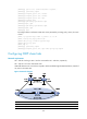
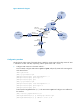
PE 1 Loop0 1.1.1.9/32
PE 2
Loop0
2.2.2.9/32
Loop1 3.3.3.3/32 Loop1 5.5.5.5/32
GE2/1
/
1 100.1.1.2/24
GE2/1
/
1 120.1.1.2/24
S2/1/2 10.1.1.1/24
S2/1/1
10.1.1.2/24
Router A S2/1/1 30.1.1.1/24
S2/1/2 20.1.1.2/24
Configuration procedure
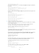
1. Configure OSPF on the customer networks:
Configure conventional OSPF on CE 1, Router A, and CE 2 to advertise segment addresses of the
interfaces as shown in Figure 97. (Details not shown.)
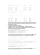
After
completing the configurations, CE 1 and CE 2 can learn the OSPF route to the Ethernet
interface of each other. Take CE 1 as an example:
<CE1> display ip routing-table
Routing Tables: Public
Destinations : 9 Routes : 9
Destination/Mask Proto Pre Cost NextHop Interface
20.1.1.0/24 Direct 0 0 20.1.1.1 S2/1/2
20.1.1.1/32 Direct 0 0 127.0.0.1 InLoop0
20.1.1.2/32 Direct 0 0 20.1.1.2 S2/1/2
30.1.1.0/24 OSPF 10 3124 20.1.1.2 S2/1/2
100.1.1.0/24 Direct 0 0 100.1.1.1 GE2/1/1
100.1.1.1/32 Direct 0 0 127.0.0.1 InLoop0
120.1.1.0/24 OSPF 10 3125 20.1.1.2 S2/1/2
127.0.0.0/8 Direct 0 0 127.0.0.1 InLoop0
127.0.0.1/32 Direct 0 0 127.0.0.1 InLoop0
2. Configure MPLS L3VPN on the backbone:
# Configure basic MPLS and MPLS LDP on PE 1 to establish LDP LSPs.
<PE1> system-view
[PE1] interface loopback 0
[PE1-LoopBack0] ip address 1.1.1.9 32
[PE1-LoopBack0] quit
[PE1] mpls lsr-id 1.1.1.9
[PE1] mpls
[PE1-mpls] quit
[PE1] mpls ldp
[PE1-mpls-ldp] quit
[PE1] interface serial 2/1/2
[PE1-Serial2/1/2] ip address 10.1.1.1 24
[PE1-Serial2/1/2] mpls
[PE1-Serial2/1/2] mpls ldp
[PE1-Serial2/1/2] quit
# Configure PE 1 to take PE 2 as the MP-IBGP peer.
[PE1] bgp 100
[PE1-bgp] peer 2.2.2.9 as-number 100
[PE1-bgp] peer 2.2.2.9 connect-interface loopback 0
[PE1-bgp] ipv4-family vpnv4