
R3303-HP HSR6800 Routers MPLS Configuration Guide
377
[PE1-GigabitEthernet2/1/1] ip binding vpn-instance vpn1
[PE1-GigabitEthernet2/1/1] ip address 100.1.1.2 24
[PE1-GigabitEthernet2/1/1] quit
[PE1] ospf 100 vpn-instance vpn1
[PE1-ospf-100] domain-id 10
[PE1-ospf-100] area 1
[PE1-ospf-100-area-0.0.0.1] network 100.1.1.0 0.0.0.255
[PE1-ospf-100-area-0.0.0.1] quit
[PE1-ospf-100] quit
[PE1] bgp 100
[PE1-bgp] ipv4-family vpn-instance vpn1
[PE1-bgp-vpn1] import-route ospf 100
[PE1-bgp-vpn1] import-route direct
[PE1-bgp-vpn1] quit
[PE1-bgp] quit
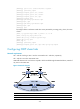
# Configure PE 2 to allow CE 2 to access the network.
[PE2] ip vpn-instance vpn1
[PE2-vpn-instance-vpn1] route-distinguisher 100:2
[PE2-vpn-instance-vpn1] vpn-target 1:1
[PE2-vpn-instance-vpn1] quit
[PE2] interface gigabitethernet 2/1/1
[PE2-GigabitEthernet2/1/1] ip binding vpn-instance vpn1
[PE2-GigabitEthernet2/1/1] ip address 120.1.1.2 24
[PE2-GigabitEthernet2/1/1] quit
[PE2] ospf 100 vpn-instance vpn1
[PE2-ospf-100] domain-id 10
[PE2-ospf-100] area 1
[PE2-ospf-100-area-0.0.0.1] network 120.1.1.0 0.0.0.255
[PE2-ospf-100-area-0.0.0.1] quit
[PE2-ospf-100] quit
[PE2] bgp 100
[PE2-bgp] ipv4-family vpn-instance vpn1
[PE2-bgp-vpn1] import-route ospf 100
[PE2-bgp-vpn1] import-route direct
[PE2-bgp-vpn1] quit
[PE2-bgp] quit
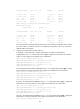
After completing the configurations, execute the display ip routing-table vpn-instance command
on the PEs, you can see that the path to the peer CE is along the OSPF route across the customer
networks, instead of the BGP route across the backbone. Take PE 1 as an example:
[PE1] display ip routing-table vpn-instance vpn1
Routing Tables: vpn1
Destinations : 5 Routes : 5
Destination/Mask Proto Pre Cost NextHop Interface
20.1.1.0/24 OSPF 10 1563 100.1.1.1 GE2/1/1
30.1.1.0/24 OSPF 10 3125 100.1.1.1 GE2/1/1
100.1.1.0/24 Direct 0 0 100.1.1.2 GE2/1/1
100.1.1.2/32 Direct 0 0 127.0.0.1 InLoop0
120.1.1.0/24 OSPF 10 3126 100.1.1.1 GE2/1/1