
R3303-HP HSR6800 Routers MPLS Configuration Guide

384
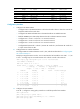
127.0.0.1/32 Direct 0 0 127.0.0.1 InLoop0
192.168.10.0/24 O_ASE 150 1 30.1.1.1 GE3/1/1.2
Now, the routing information for the two VPNs has been redistributed into the routing tables on PE 1.
Configuring BGP AS number substitution
Network requirements
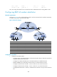
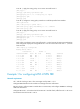
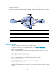
As shown in Figure 99, CE 1 and CE 2 belong to VPN 1 and are connected to PE 1 and PE 2 respectively.
In addition, they use the same AS number 600.
Figure 99 Network diagram
Device Interface IP address
Device
Interface
IP address
CE 1 GE2/1
/
1 10.1.1.1/24
P
Loop0
2.2.2.9/32
GE2/1/2 100.1.1.1/24 GE2/1/1 20.1.1.2/24
PE 1 Loop0 1.1.1.9/32
GE2/1
/
2 30.1.1.1/24
GE2/1
/
1 10.1.1.2/24
PE 2
Loop0
3.3.3.9/32
GE2/1/2 20.1.1.1/24 GE2/1/1 10.2.1.2/24
CE 2 GE2/1
/
1 10.2.1.1/24
GE2/1
/
2 30.1.1.2/24
GE2/1
/
2 200.1.1.1/24
Configuration procedure
1. Configure basic MPLS L3VPN:
{ Configure OSPF on the MPLS backbone to allow the PEs and P device to learn the routes of the
loopback interfaces from each other.
{ Configure basic MPLS and MPLS LDP on the MPLS backbone to establish LDP LSPs.
{ Establish MP-IBGP peer relationship between the PEs to advertise VPN IPv4 routes.
{ Configure the VPN instance of VPN 1 on PE 2 to allow CE 2 to access the network.
{ Configure the VPN instance of VPN 1 on PE 1 to allow CE 1 to access the network.
{ Configure BGP between PE 1 and CE 1, and between PE 2 and CE 2 to inject routes of CEs into
PEs.