
R3303-HP HSR6800 Routers MPLS Configuration Guide

387
200.1.1.1/32 Direct 0 0 127.0.0.1 InLoop0
After you also configure BGP AS substitution on PE 1, the GigabitEthernet interfaces of CE 1 and
CE 2 can ping each other:
<CE1> ping –a 100.1.1.1 200.1.1.1
PING 200.1.1.1: 56 data bytes, press CTRL_C to break
Reply from 200.1.1.1: bytes=56 Sequence=1 ttl=253 time=109 ms
Reply from 200.1.1.1: bytes=56 Sequence=2 ttl=253 time=67 ms
Reply from 200.1.1.1: bytes=56 Sequence=3 ttl=253 time=66 ms
Reply from 200.1.1.1: bytes=56 Sequence=4 ttl=253 time=85 ms
Reply from 200.1.1.1: bytes=56 Sequence=5 ttl=253 time=70 ms
--- 200.1.1.1 ping statistics ---
5 packet(s) transmitted
5 packet(s) received
0.00% packet loss
round-trip min/avg/max = 66/79/109 ms
Configuring BGP AS number substitution and SoO
Network requirements
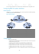
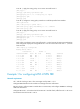
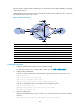
CE 1, CE 2, and CE 3 belong to VPN 1 and connect to PE1, PE 2, and PE 3 respectively.
CE 1 and CE 2 reside in the same site. CE1, CE2, and CE 3 all use AS number 600.
To avoid route loss, configure BGP AS number substitution on PEs. To avoid routing loops, configure a
routing policy on PE1 and PE2 respectively to add the SoO attribute to routes received from CE 1 and CE
2.
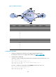
Figure 100 Network diagram
Device Interface IP address
Device
Interface
IP address
CE 1 Loop0 100.1.1.1/32
CE 3
Loop0
200.1.1.1/32
GE2/1/1 10.1.1.1/24 GE2/1/1 10.3.1.1/24
CE 2 GE2/1
/
1 10.2.1.1/24
PE 2
Loop0
2.2.2.9/32
Loop0
Loop0
Loop0
PE 1
P
PE 3
CE 2
CE 3
VPN 1
AS 600
VPN 1
AS 600
GE2/1/2
GE2/1/2
GE2/1/3
GE2/1/1
GE2/1/1
GE2/1/1
GE2/1/1
GE2/1/1
MPLS backbone
AS 100
CE 1
GE2/1/1
GE2/1/1
Loop0
GE2/1/2
GE2/1/3
GE2/1/3
GE2/1/2
PE 2
Loop0
Loop0