
R3303-HP HSR6800 Routers MPLS Configuration Guide

392
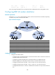
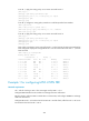
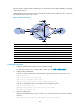
Between the PEs, configure OSPF to enable them to communicate, and configure MP-IBGP to exchange
VPN route information.
Configure FRR on PE 2 so that when the link between PE 2 and CE 2 fails, traffic from CE 1 to CE 2 can
be switched to the link PE 2—PE 3—CE2.
Figure 102 Network diagram
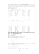
Device Interface IP address
Device
Interface
IP address
CE 1 GE 2/1/1 10.2.1.1/24 PE 2 Loop0 2.2.2.2/32
PE 1 Loop0 1.1.1.1/32
GE
2
/
1/1 172.1.1.2/24
GE
2
/
1/1 10.2.1.2/24
GE
2
/
1/2 10.1.1.2/24
GE 2/1/2 172.1.1.1/24 GE 2/1/3 172.3.1.1/24
GE
2
/
1/3 172.2.1.1/24
PE 3
Loop0
3.3.3.3/32
CE 2 Loop0 4.4.4.4/32
GE
2
/
1/1 172.2.1.2/24
GE 2/1/1 10.1.1.1/24 GE 2/1/2 10.3.1.2/24
GE
2
/
1/2 10.3.1.1/24
GE
2
/
1/3 172.3.1.2/24
Configuration procedure
1. Configure IP addresses for interfaces, BGP, and MPLS L3VPN:
For information about how to configure MPLS L3VPN, see see "错误!未找到引用源。."
2. Configure MPLS L3VPN FRR:
# On PE 2, create a routing policy named vpnfrr to specify the backup next hop as 3.3.3.3.
<PE2> system-view
[PE2] bfd echo-source-ip 54.54.54.54
[PE2] route-policy vpnfrr permit node 10
[PE2-route-policy] apply fast-reroute backup-nexthop 3.3.3.3
# On PE 2, enable FRR in VPN 1 and reference the routing policy vpnfrr.
[PE2] ip vpn-instance vpn1
[PE2-vpn-instance-vpn1] fast-reroute route-policy vpnfrr
[PE2-vpn-instance-vpn1] quit
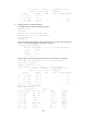
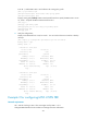
3. Verify the configuration:
Display routes destined for 4.4.4.4/32 on PE 2. You can see that the active route has a backup
next hop.
[PE2] display ip routing-table vpn-instance vpn1 4.4.4.4 verbose