
R3303-HP HSR6800 Routers MPLS Configuration Guide

395
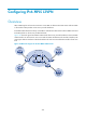
IPv6 MPLS L3VPN packet forwarding
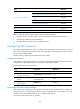
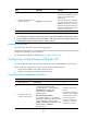
Figure 104 IPv6 MPLS L3VPN packet forwarding diagram
As shown in Figure 104, the IPv6 MPLS L3VPN packet forwarding procedure is as follows:
1. The PC at Site 1 sends an IPv6 packet destined for 2001:2::1, the PC at Site 2. CE 1 transmits the
packet to PE 1.
2. Based on the inbound interface and destination address of the packet, PE 1 searches the routing
table of the VPN instance. Finding a matching entry, PE 1 labels the packet with both inner and
outer labels and forwards the packet out.
3. The MPLS backbone transmits the packet to PE 2 by outer label. The outer label is removed from
the packet at the penultimate hop.
4. According to the inner label and destination address of the packet, PE 2 searches the routing table
of the VPN instance to determine the outbound interface and then forwards the packet out of the
interface to CE 2.
5. CE 2 forwards the packet to the destination by IPv6 forwarding.
IPv6 MPLS L3VPN routing information advertisement
The IPv6 VPN routing information for a local CE is advertised to a remote peer PE in the following steps:
1. From the local CE to the ingress PE.
2. From the ingress PE to the egress PE.
3. From the egress PE to the remote peer CE.
A route becomes available from the local CE to the remote CE.
Routing information exchange from the local CE to the ingress PE
After establishing an adjacency with the directly connected PE, a CE advertises its IPv6 VPN routes to the
PE.
The routes between a CE and a PE can be IPv6 static routes, RIPng routes, OSPFv3 routes, IPv6 IS-IS
routes, or EBGP routes. No matter which routing protocol is used, the CE always advertises standard IPv6
routes to the PE.