
R3303-HP HSR6800 Routers MPLS Configuration Guide
418
[PE2-LoopBack0] quit
[PE2] interface pos 5/1/1
[PE2-POS5/1/1] ip address 172.2.1.2 24
[PE2-POS5/1/1] quit
[PE2] ospf
[PE2-ospf-1] area 0
[PE2-ospf-1-area-0.0.0.0] network 172.2.1.0 0.0.0.255
[PE2-ospf-1-area-0.0.0.0] network 3.3.3.9 0.0.0.0
[PE2-ospf-1-area-0.0.0.0] quit
[PE2-ospf-1] quit
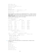
After the configurations, OSPF adjacencies are established between PE 1, P, and PE 2. Execute the
display ospf peer command. The output shows that the adjacency is in the Full state. Execute the
display ip routing-table command. The output shows that the PEs have learned the routes to the
loopback interfaces of each other. Take PE 1 as an example:
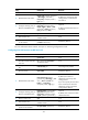
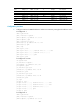
[PE1] display ip routing-table
Routing Tables: Public
Destinations : 9 Routes : 9
Destination/Mask Proto Pre Cost NextHop Interface
1.1.1.9/32 Direct 0 0 127.0.0.1 InLoop0
2.2.2.9/32 OSPF 10 1 172.1.1.2 POS5/1/1
3.3.3.9/32 OSPF 10 2 172.1.1.2 POS5/1/1
127.0.0.0/8 Direct 0 0 127.0.0.1 InLoop0
127.0.0.1/32 Direct 0 0 127.0.0.1 InLoop0
172.1.1.0/24 Direct 0 0 172.1.1.1 POS5/1/1
172.1.1.1/32 Direct 0 0 127.0.0.1 InLoop0
172.1.1.2/32 Direct 0 0 172.1.1.2 POS5/1/1
172.2.1.0/24 OSPF 10 1 172.1.1.2 POS5/1/1
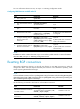
[PE1] display ospf peer verbose
OSPF Process 1 with Router ID 1.1.1.9
Neighbors
Area 0.0.0.0 interface 172.1.1.1(POS5/1/1)'s neighbors
Router ID: 172.1.1.2 Address: 172.1.1.2 GR State: Normal
State: Full Mode:Nbr is Master Priority: 1
DR: None BDR: None MTU: 1500
Dead timer due in 38 sec
Neighbor is up for 00:02:44
Authentication Sequence: [ 0 ]
Neighbor state change count: 5
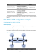
2. Configure basic MPLS and enable MPLS LDP on the MPLS backbone to establish LDP LSPs:
# Configure PE 1.
[PE1] mpls lsr-id 1.1.1.9
[PE1] mpls
[PE1-mpls] quit
[PE1] mpls ldp
[PE1-mpls-ldp] quit
[PE1] interface pos 5/1/1
[PE1-POS5/1/1] mpls
[PE1-POS5/1/1] mpls ldp