
R3303-HP HSR6800 Routers MPLS Configuration Guide

429
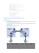
A
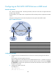
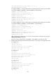
SBR-PE1 Loop0 2.2.2.9/32
A
SBR-PE2
Loop0 3.3.3.9/32
POS5/1/1 172.1.1.1/24 POS5/1/1 162.1.1.1/24
POS5/1/2 2002:1::1/96
POS5/1/2 2002:1::2/96
Configuration procedure
1. Configure an IGP on each MPLS backbone to ensure IP connectivity within the backbone:
This example uses OSPF. Be sure to advertise the route to the 32-bit loopback interface address of
each router through OSPF. The loopback interface address of a router is to be used as the router's
LSR ID. (Details not shown.)
After the configurations, each ASBR PE and the PE in the same AS can establish an OSPF
adjacency. Execute the display ospf peer command and ping command. You can see that the
adjacencies are in Full state, and that the PE and ASBR PE in the same AS have learned the routes
to the loopback interfaces of each other and can ping each other.
2. Configure basic MPLS and enable MPLS LDP on each MPLS backbone to establish LDP LSPs:
# Configure basic MPLS on PE 1 and enable MPLS LDP for both PE 1 and the interface connected
to ASBR-PE 1.
<PE1> system-view
[PE1] mpls lsr-id 1.1.1.9
[PE1] mpls
[PE1-mpls] quit
[PE1] mpls ldp
[PE1-mpls-ldp] quit
[PE1] interface pos 5/1/1
[PE1-POS5/1/1] mpls
[PE1-POS5/1/1] mpls ldp
[PE1-POS5/1/1] quit
# Configure basic MPLS on ASBR-PE 1 and enable MPLS LDP for both ASBR-PE 1 and the interface
connected to PE 1.
<ASBR-PE1> system-view
[ASBR-PE1] mpls lsr-id 2.2.2.9
[ASBR-PE1] mpls
[ASBR-PE1-mpls] quit
[ASBR-PE1] mpls ldp
[ASBR-PE1-mpls-ldp] quit
[ASBR-PE1] interface pos 5/1/1
[ASBR-PE1-POS5/1/1] mpls
[ASBR-PE1-POS5/1/1] mpls ldp
[ASBR-PE1-POS5/1/1] quit
# Configure basic MPLS on ASBR-PE 2 and enable MPLS LDP for both ASBR-PE 2 and the interface
connected to PE 2.
<ASBR-PE2> system-view
[ASBR-PE2] mpls lsr-id 3.3.3.9
[ASBR-PE2] mpls
[ASBR-PE2-mpls] quit
[ASBR-PE2] mpls ldp
[ASBR-PE2-mpls-ldp] quit
[ASBR-PE2] interface pos 5/1/1