
R3303-HP HSR6800 Routers MPLS Configuration Guide
439
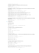
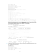
[PE1] ping ipv6 –vpn-instance vpn1 2001:1::2
PING 2001:1::2 : 56 data bytes, press CTRL_C to break
Reply from 2001:1::2
bytes=56 Sequence=1 hop limit=64 time = 1 ms
Reply from 2001:1::2
bytes=56 Sequence=2 hop limit=64 time = 1 ms
Reply from 2001:1::2
bytes=56 Sequence=3 hop limit=64 time = 1 ms
Reply from 2001:1::2
bytes=56 Sequence=4 hop limit=64 time = 1 ms
Reply from 2001:1::2
bytes=56 Sequence=5 hop limit=64 time = 1 ms
--- 2001:1::2 ping statistics ---
5 packet(s) transmitted
5 packet(s) received
0.00% packet loss
round-trip min/avg/max = 1/1/1 ms
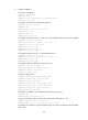
Configuring carrier's carrier
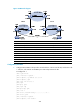
Network requirements
Configure carrier's carrier for the scenario shown in Figure 109. In this scenario:
• PE 1 and PE 2 are the provider carrier's PE routers. They provide VPN services to the customer
carrier.
• CE 1 and CE 2 are the customer carrier's routers. They are connected to the provider carrier's
backbone as CE routers.
• PE 3 and PE 4 are the customer carrier's PE routers. They provide IPv6 MPLS L3VPN services to end
customers.
• CE 3 and CE 4 are customers of the customer carrier.
The key to the carrier's carrier deployment is to configure exchange of two kinds of routes:
• Exchange of the customer carrier's internal routes on the provider carrier's backbone.
• Exchange of the end customers' internal routes between PE 3 and PE 4, the PEs of the customer
carrier. In this process, an MP-IBGP peer relationship must be established between PE 3 and PE 4.