
R3303-HP HSR6800 Routers MPLS Configuration Guide

49
• Standard backup where a secondary CR-LSP is created to take over after the primary CR-LSP fails.
FRR
FRR provides a quick per-link or per-node protection on an LSP.
In this method, once a link or node fails on a path, FRR comes up to reroute the path to a new link or node
to bypass the failed link or node. This can happen in as fast as 50 milliseconds, thereby minimizing data
loss.
Once a link or node on an LSP configured with FRR fails, traffic is switched to the protection link and the
ingress node of the LSP starts attempting to set up a new LSP.
Basic concepts
The following are some basic concepts of FRR:
• Protected LSP—A primary LSP to be protected.
• Bypass LSP—An LSP used to protect primary LSPs.
• Point of local repair—An PLR is the ingress node of a bypass LSP. It must be located on a protected
LSP but must not be the egress node.
• Merge point—An MP is the egress node of the bypass LSP. It must be located on a protected LSP but
must not be the ingress node.
Protection
FRR provides link protection and node protection for an LSP.
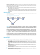
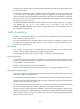
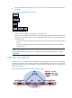
• Link protection—The PLR and the MP are connected through a direct link and the primary LSP
traverses this link. When the link fails, traffic is switched to the bypass LSP. As shown in Figure 18,
the pr
imary LSP is Router A → Router B → Router C → Router D, and the bypass LSP is Router B →
Router F → Router C.
Figure 18 FRR link protection
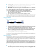
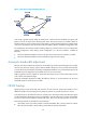
• Node protection—The PLR and the MP are connected through a device and the primary LSP
traverses this device. When the device fails, traffic is switched to the bypass LSP. As shown in Figure
19, the pr
imary LSP is Router A → Router B → Router C → Router D → Router E, and the bypass LSP
is Router B → Router F→ Router D. Router C is the protected device.