
R3303-HP HSR6800 Routers MPLS Configuration Guide

51
• The prestandard mode is proprietary, and therefore a device operating in prestandard mode
cannot communicate with devices of some other vendors. The IETF mode is a standard mode
implemented according to relative RFCs. A device operating in IETF mode can communicate with
devices of other vendors.
How DS-TE operates
A device takes the following steps to establish MPLS TE tunnels according to CTs of traffic trunks:
1. Determines the CT of traffic flows.
A device classifies traffic flows according to your configuration:
{ When configuring a dynamic MPLS TE tunnel, you can use the mpls te bandwidth command on
the tunnel interface to specify a CT for the traffic flows to be forwarded by the tunnel.
{ When configuring a static MPLS TE tunnel, you can use the bandwidth keyword to specify a CT
for the traffic flows to be forwarded along the tunnel.
2. Checks whether bandwidth is enough for the CT.
You can use the mpls te max-reservable-bandwidth command on an MPLS TE tunnel interface to
configure the bandwidth constraints of the tunnel interface. The device determines whether
bandwidth is enough to establish an MPLS TE tunnel for a traffic trunk according to the traffic
trunk's CT and the tunnel interface's BCs.
The relation between BCs and CTs varies in different BC models:
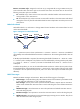
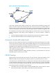
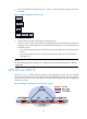
In RDM model, a BC constrains the total bandwidth of multiple CTs, as shown in Figure 20:
• B
C 2 is for CT 2. The total bandwidth of the traffic of CT 2 cannot exceed BC 2.
• BC 1 is for CT 2 and CT 1. The total bandwidth of the traffic of CT 2 and CT 1 cannot exceed BC
1.
• BC 0 is for CT 2, CT 1, and CT 0. The total bandwidth of the traffic of CT 2, CT 1, and CT 0 cannot
exceed BC 0. In this model, BC 0 equals the maximum reservable bandwidth of the tunnel.
In cooperation with priority preemption, the RDM model can also implement the isolation across CTs,
ensuring each CT its share of bandwidth. RDM is suitable for networks where traffic is unstable and traffic
bursts might occur.
Figure 20 RDM bandwidth constraints model
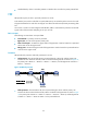
In MAM model, a BC constrains the bandwidth of only one CT on an interface. This ensures isolation
across CTs no matter whether preemption is used or not. Compared with RDM, MAM is easy to
understand and configure. MAM is suitable for networks where traffic of each CT is stable. Figure 21
sh
ows an example:
• BC 0 is for CT 0. The bandwidth occupied by the traffic of CT 0 cannot exceed BC 0.
• BC 1 is for CT 1. The bandwidth occupied by the traffic of CT 1 cannot exceed BC 1.
• BC 2 is for CT 2. The bandwidth occupied by the traffic of CT 2 cannot exceed BC 2.