
R3303-HP HSR6800 Routers MPLS Configuration Guide
89
[RouterB] interface giabitethernet 2/1/1
[RouterB-GigabitEthernet2/1/1] mpls
[RouterB-GigabitEthernet2/1/1] mpls te
[RouterB-GigabitEthernet2/1/1] quit
[RouterB] interface giabitethernet 2/1/2
[RouterB-GigabitEthernet2/1/2] mpls
[RouterB-GigabitEthernet2/1/2] mpls te
[RouterB-GigabitEthernet2/1/2] quit
# Configure Router C.
[RouterC] mpls lsr-id 3.3.3.3
[RouterC] mpls
[RouterC-mpls] mpls te
[RouterC-mpls] quit
[RouterC] interface giabitethernet 2/1/1
[RouterC-GigabitEthernet2/1/1] mpls
[RouterC-GigabitEthernet2/1/1] mpls te
[RouterC-GigabitEthernet2/1/1] quit
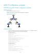
4. Configure an MPLS TE tunnel:
# Configure an MPLS TE tunnel on Router A.
[RouterA] interface tunnel 0
[RouterA-Tunnel0] ip address 6.1.1.1 255.255.255.0
[RouterA-Tunnel0] tunnel-protocol mpls te
[RouterA-Tunnel0] destination 3.3.3.3
[RouterA-Tunnel0] mpls te tunnel-id 10
[RouterA-Tunnel0] mpls te signal-protocol static
[RouterA-Tunnel0] mpls te commit
[RouterA-Tunnel0] quit
5. Create a static CR-LSP:
# Configure Router A as the ingress node of the static CR-LSP.
[RouterA] static-cr-lsp ingress tunnel0 destination 3.3.3.3 nexthop 2.1.1.2 out-label
20
# Configure Router B as the transit node on the static CR-LSP.
[RouterB] static-cr-lsp transit tunnel0 incoming-interface giabitethernet 2/1/1
in-label 20 nexthop 3.2.1.2 out-label 30
# Configure Router C as the egress node of the static CR-LSP.
[RouterC] static-cr-lsp egress tunnel0 incoming-interface giabitethernet 2/1/1
in-label 30
6. Verify the configuration:
Execute the display interface tunnel command on Router A. You can see that the tunnel interface is
up.
[RouterA] display interface tunnel
Tunnel0 current state: UP
Line protocol current state: UP
Description: Tunnel0 Interface
The Maximum Transmit Unit is 64000
Internet Address is 6.1.1.1/24 Primary
Encapsulation is TUNNEL, service-loopback-group ID not set