
R3303-HP HSR6800 Routers MPLS Configuration Guide

91
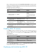
Name FEC I/O Label I/O If State
Tunnel0 -/- 20/30 GE2/1/1/GE2/1/2 Up
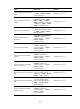
[RouterC] display mpls static-cr-lsp
total statics-cr-lsp : 1
Name FEC I/O Label I/O If State
Tunnel0 -/- 30/NULL GE2/1/1/- Up
On an MPLS TE tunnel configured using a static CR-LSP, traffic is forwarded directly based on label
at the transit nodes and egress node. Therefore, it is normal that the FEC field in the sample output
is empty on Router B and Router C.
7. Create a static route to direct traffic to the MPLS TE tunnel:
[RouterA] ip route-static 3.2.1.2 24 tunnel 0 preference 1
Execute the display ip routing-table command on Router A. You can see a static route entry with
interface Tunnel0 as the outgoing interface.
MPLS TE tunnel using RSVP-TE configuration example
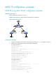
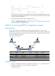
Network requirements
Router A, Router B, Router C, and Router D are running IS-IS and all of them are Level-2 routers.
Use RSVP-TE to create a TE tunnel with 2000 kbps of bandwidth from Router A to Router D, making sure
that the maximum bandwidth of each link that the tunnel traverses is 10000 kbps and the maximum
reservable bandwidth is 5000 kbps.
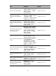
Figure 25 Network diagram
Device Interface IP address
Device
Interface
IP address
Router A Loop0 1.1.1.9/32
Router C
Loop0
3.3.3.9/32
GE 2/1/1 10.1.1.1/24 GE 2/1/1 30.1.1.1/24
Router B Loop0 2.2.2.9/32
POS
5/1/0 20.1.1.2/24
GE 2/1/1 10.1.1.2/24
Router D
Loop0
4.4.4.9/32
POS 5/1/0 20.1.1.1/24 GE 2/1/1 30.1.1.2/24
Configuration procedure
1. Configure IP addresses and masks for the interfaces according to Figure 25. (Details not shown.)
2. Enable IS-IS to advertise host routes with LSR IDs as destinations:
# Configure Router A.
<RouterA> system-view