
R3303-HP HSR6800 Routers Network Management and Monitoring Configuration Guide


71
NTP broadcast mode configuration example
Network requirements
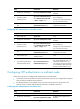
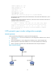
As shown in Figure 28, Router C functions as the NTP server for multiple devices on a network segment
and synchronizes the time among multiple devices.
• Router C’s local clock is to be used as a reference source, with the stratum level 2.
• Router C operates in broadcast server mode and sends broadcast messages from GigabitEthernet
2/0/1.
• Router B and Router A operate in broadcast client mode and receive broadcast messages through
their respective GigabitEthernet 2/0/1.
Figure 28 Network diagram
Configuration procedure
1. Set the IP address for each interface as shown in Figure 28. (Details not shown.)
2. Configure Router C:
# Specify the local clock as the reference source, with the stratum level 2.
<RouterC> system-view
[RouterC] ntp-service refclock-master 2
# Configure Router C to operate in broadcast server mode and send broadcast messages through
GigabitEthernet 2/0/1.
[RouterC] interface gigabitethernet 2/0/1
[RouterC-GigabitEthernet2/0/1] ntp-service broadcast-server
3. Configure Router A:
# Configure Router A to operate in broadcast client mode and receive broadcast messages on
GigabitEthernet 2/0/1.
<RouterA> system-view
[RouterA] interface gigabitethernet 2/0/1
[RouterA-GigabitEthernet2/0/1] ntp-service broadcast-client
4. Configure Router B: