HP HSR6800 Routers Installation Guide 5998-4040 Part number: 5998-4040 Document version: 6PW102-20140210
Legal and notice information © Copyright 2014 Hewlett-Packard Development Company, L.P. No part of this documentation may be reproduced or transmitted in any form or by any means without prior written consent of Hewlett-Packard Development Company, L.P. The information contained herein is subject to change without notice.
Contents Preparing for installation ············································································································································· 1 Safety recommendations ·················································································································································· 1 Safety symbols ·················································································································································
Transceiver module overview ······························································································································· 28 Fiber cable overview ············································································································································· 29 Connecting a fiber cable ······································································································································ 30 Connecting an E1/T1 cabl
Displaying the fan operating status ····················································································································· 60 Displaying the power module operating status ·································································································· 61 Displaying the alarming thresholds of a card ············································································································· 61 Port configuration and management·················
DC power module ················································································································································· 87 Fan tray specifications ··················································································································································· 89 MPU ········································································································································································
Preparing for installation The HP HSR6800 routers include the following models: HSR6802, HSR6804, and HSR6808.
Electricity safety • Locate the emergency power-off switch in the room before installation. Shut the power off at once in case accident occurs. Disconnect the power cord of the router if necessary. • Use an uninterrupted power supply (UPS). • Do not work alone when the router has power. Do not touch any power plug when it is connected. • Always make sure the power has been disconnected during the installation and replacement.
• If the router needs to be moved over a long distance, remove all field replacement units (FRUs), such as HIMs/MIMs, put them separately in anti-static bags, and install the filler panels supplied with router. • If the router needs to be moved over a short distance, make sure all FRUs are securely seated in slots and the screws are fastened. • Make sure the accessories of the router are not lost or damaged during router moving.
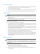
Figure 1 Attaching an ESD wrist strap (1) ESD wrist strap (2) Lock (3) ESD plug CAUTION: Check the resistance of the ESD wrist strap for safety. The resistance reading should be in the range of 1 to 10 megohm (Mohm) between human body and the ground. Examining the installation site The routers can only be used indoors.
Table 2 Temperature requirements Item Temperature Operating temperature 0°C to 45°C (32°F to 113°F) Storage temperature –40°C to +70°C (–40°F to +158°F) Humidity Maintain appropriate humidity in your equipment room, as described in Table 3. • Lasting high relative humidity tends to cause poor insulation, electricity creepage, mechanical property change of materials, and corrosion of metal parts.
Table 6 Harmful gas limits in an equipment room Gas Max. (mg/m3) SO2 0.2 H2S 0.006 NH3 0.05 Cl2 0.01 Cooling system Fan trays of the routers are hot swappable and support automatic fan speed adjustment. To ensure good ventilation, the following requirements must be met: • Leave at least 10 cm (3.94 in) of clearance at the inlet and outlet air vents. • The installation site has a good cooling system.
Figure 3 Airflow through the HSR6808 chassis EMI Electromagnetic interference (EMI) might be coupled from the source to the router through the following coupling mechanisms: • Capacitive coupling • Inductive coupling • Radiative coupling • Common impedance coupling • Conductive coupling To prevent EMI, take the following actions: • Take measures against interference from the power grid.
Lightning protection To protect the router from lightning better, do as follows: • Make sure the grounding cable of the chassis is well grounded. For how to connect the grounding cable, see "Grounding the router." • Make sure the grounding terminal of the AC power receptacle is well grounded. • Install a lightning arrester at the input end of the power supply to enhance the lightning protection capability of the power supply.
Mounting brackets for the HSR6808 (supplied with the router) Cable management bracket for the HSR6808 (supplied with the router) M6 cage nut (supplied with the router) ESD gloves (user-supplied) 9 M6 screws (supplied with the router) Cable tie (user-supplied)
Installing the router Installation flow Figure 4 Installation flow Start Unpacking the router Install a cable management bracket (only on HSR6808 router) Install the router to a 19-inch rack Ground the router Install a power module Install an MPU and a switching fabric module Install an LPU Install a HIM/MIM Install a CF card Install optional components Connect the power cord End Installing a cable management bracket The cable management brackets of the HSR6802 and HSR6804 are provided with mount
Figure 5 Installing a cable management bracket Installing the router in a 19-inch rack The procedures for installing an HSR6800 router in a rack are similar. This section uses an HSR6802 router as an example. To install the router in a rack, you need mounting brackets and a rack shelf. Installing cage nuts to the rack 1. Locate the installation position for the router and then install a rack shelf to the rack. 2.
Figure 6 Marking the positions of cage nuts 5RU 5RU 3. Insert one edge of a cage nut into the hole. 4. Use a flat-blade screwdriver to compress the other edge of the cage nut, and then push the cage nut fully into the hole. 5. Repeat steps 3 and 4 to install other cage nuts to all the marked positions on the rack post. Figure 7 Installing a cage nut Installing the mounting brackets to the router If you have ordered an air filter, install it to the router before you install the mounting brackets.
Figure 8 Installing the front mounting brackets to the two sides of the router Installing the router in a 19-inch rack 1. Put the router on the rack shelf. 2. Slide the router into the rack so the screw holes on the mounting brackets are aligned with holes that are installed with cage nuts on the rack posts. 3. Use M6 screws to attach the mounting brackets to the rack posts. Make sure the rack shelf is even and stable.
1. Remove the two grounding screws from the rear panel of the chassis. 2. Attach the grounding screw to the OT terminal of the grounding cable. 3. Use a Phillips screwdriver to fasten the grounding screw into the grounding screw hole. 4. Connect the other end of the grounding cable to the grounding strip of the rack. Figure 10 Connecting the grounding cable to the grounding hole of router IMPORTANT: • The resistance reading should be smaller than 5 ohms between the chassis and the ground.
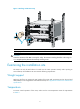
Figure 11 Installing a power module Installing an MPU and a switching fabric module Installing an RSE-X2 MPU CAUTION: The RUN LED flashes fast when the MPU is starting up. Do not install or remove the MPU during this period. Otherwise, hardware might be damaged. Before the installation, make sure the ejector levers of the MPU are outwards. The Slot 4 of the HSR6808 is not provided with a filler panel. To install an RSE-X2 MPU: 1. Face the front of the router and locate the slot to be used. 2.
1. Face the front of the router and locate the slot. 2. Loosen the captive screws with a Phillips screwdriver to remove the filler panel from the slot. Keep the removed filler panel for future use. 3. Insert the SFE-X1 slowly along the slide rails until positioning pins on the backplane are seated in the positioning holes, and then push the ejector levers inward to lock the SFE-X1 in position. 4. Use a Phillips screwdriver to fasten the captive screws on the two sides of the SFE-X1.
To install a FIP-210: 1. Face the front of the router and locate the slot to be used. 2. Loosen the captive screws with a Phillips screwdriver to remove the filler panel from the slot. Keep the removed filler panel for future use. Skip this step if you install the FIP-210 to Slot 3 of the HSR6802/HSR6804, or Slot 7 of the HSR6808. 3.
Figure 15 Pushing the MIM into the slot Installing a CF card 1. Push the CF card eject button all the way into the slot, and make sure the button does not project from the panel. 2. Insert the CF card into the slot following the direction shown in Figure 16, and make sure it does not project from the slot. Figure 16 Inserting the CF card into the slot Installing optional components Optional components (including the air filter) are not provided with the router. Purchase them if necessary.
2. Install the upper and lower slide rails on the chassis as shown in Figure 17. 3. Use a Phillips screwdriver to fasten the fastening screws on the upper and lower slide rails. Figure 17 Installing the upper and lower slide rails 4. Push the air filter along the slide rails from the rear side of the chassis to the front. Figure 18 Inserting the air filter to the slide rail 5. Use a Phillips screwdriver to fasten the captive screws on the rear side of the air filter.
Figure 19 Fastening the captive screws Installing an air filter on an HSR6808 1. Face the front of the router. 2. Align the positioning pins on the air filter with the screw holes on the inlet vent area, and use a Phillips screwdriver to fasten the screws on the air filter. Figure 20 Installing an air filter on an HSR6808 Connecting the power cord Connecting an AC power cord 1. Make sure the router is well grounded, and the power switch on the router is in the OFF position. 2.
Figure 21 Connecting an AC power cord to the router Connecting DC power cords Connecting power cords for the PSR650-D WARNING! To avoid connection mistakes, identify the label on the DC power cord. Figure 22 DC power cords To connect DC power cords: 1. Switch off the power supply. 2. Remove the protection cover of the DC power module, and use a Phillips screwdriver to remove the screws from the DC-input terminal block. 3.
Figure 23 Connecting DC power cords Connecting power cords for the PSR1200-D Figure 24 DC power cords - + To connect DC power cords: 1. Loosen the captive screws on the power module with a Phillips screwdriver to remove the power module connector.
Figure 25 Removing the power module connector. 2. Connect the end marked with "– " to the negative terminal (–) on the power module connector and fasten the fastening screw. 3. Connect the end marked with "+"to the positive terminal (+) on the power module connector and fasten the fastening screw. Figure 26 Attaching the power cords to the power module connector 4. Insert the power module connector in right direction into the power module, and fasten the captive screws with a Phillips screwdriver.
Figure 27 Installing the power module connector to the power module 5. Connect the other end of each power cord to the DC power source. 6. Use cable ties to secure the power cords to the rack post.
Connecting interface cables Connecting the AUX cable Overview An AUX cable has a crimped RJ-45 connector at one end for connecting to the AUX port of the router, and D9 male connectors at the other end for connecting to the serial port of the modem. Figure 28 AUX cable Connecting the AUX cable 1. Plug the D9 male connector at one end of the AUX cable into the serial port of the modem. 2. Plug the RJ-45 connector of the AUX cable into the AUX port of the router.
Connecting an Ethernet cable Overview 10/100 Mbps Ethernet uses category-5 twisted pair cables, while 1000 Mbps Ethernet uses category-5 enhanced or category-6 twisted pair cables. Twisted pair cables include straight-through cables and crossover cables. Category-5 cables provide a transmission frequency of 100 MHz for voice and data transmission; they are mainly used in 100Base-T and 10Base-T networks. Category-5 cables are common Ethernet cables, which can also be used to transmit 1000 Mbps Ethernet data.
For the pinouts of the twisted pair cables, see the following tables. (A and B represent the two ends of a cable, respectively.) Table 7 Straight-through cable pinouts Pinout No. A B 1 Orange/white Orange/white 2 Orange Orange 3 Green/white Green/white 4 Blue Blue 5 Blue/white Blue/white 6 Green Green 7 Brown/white Brown/white 8 Brown Brown Table 8 Crossover cable pinouts Pinout No.
Connecting an Ethernet cable 1. Plug one end of an Ethernet twisted pair cable into the copper Ethernet port (RJ-45 port) or the management Ethernet port to be connected on the router and the other end of the cable into the Ethernet port of the peer device. The 10/100/1000Base-T copper ports of the router support MDI/MDI-X auto-sensing. They are connected to the network through category-5 or above twisted pairs that are equipped with RJ-45 connectors. 2. Examine the status LED of the Ethernet ports.
Figure 33 SFP+ transceiver module Fiber cable overview CAUTION: • Never exert a fierce force when you insert or remove a fiber connector. • Never pull, press or extrude the fiber fiercely. Optical fibers can be classified into single-mode optical fibers and multi-mode optical fibers. A single-mode optical fiber carries only a single ray of light, and a multi-mode optical fiber carries multiple modes of lights.
Figure 34 LC connector 2 1 (1) LC connector (2) Optical fiber Connecting a fiber cable WARNING! Do not stare into any fiber port when you connect an optical fiber. The laser light emitted from the optical fiber might hurt your eyes. To connect a fiber cable: 1. Remove the dust plug from a fiber port of the router. 2. Remove the dust cover from the transceiver module, and plug the end without a pull latch into the fiber port. 3. Remove the dust cover from the fiber connector. 4.
Figure 35 Connecting a fiber cable 5. Examine the LINK LED after connection. { { If the LED is on, the optical fiber link is present. If the LED is off, no link is present. This might be because the TX and Rx port of the optical fiber are not connected correctly. In this case, connect the optical fiber again. Connecting an E1/T1 cable Overview E1 cable You can use an 8E1 interface cable to connect to MIM-8E1(75)/MIM-8E1(75)-F modules.
NOTE: The coaxial connector and 75-ohm E1 adapter cable are optional accessories, and must be purchased separately if needed. T1 cable CAUTION: • When connecting the interface cable, pay attention to the mark on the interface to avoid wrong insertion, which might damage the interface module or even the router. • HP recommends that you install a lightning protector at the input end of the 8T1 cables to protect them against lightning strikes more efficiently when they are led outdoors.
Figure 38 Connecting an E1 75-ohm cable …… If you want to extend the cable, connect each BNC connector of the E1 75-ohm cable to one end of a coaxial connector, and connect the remote device to the other end of the coaxial connector through an E1 75-ohm adapter cable. • Figure 39 Connecting an E1 75-ohm cable If the impedance of the E1 interface on the remote device is 120 ohms, you must use an impedance converter to adapt the impedance.
2. The other end of the cable provides eight RJ-45 connectors. Connect them to the RJ-45 interface on the remote device as needed. Figure 41 Connecting an 8T1 cable Connecting a CE3/CT3 cable Overview CAUTION: HP recommends that you install a special lightning protector at the input end of the E3/T3 cables to protect them against lightning strikes more efficiently when they are routed outdoors. You can use a E3/T3 interface cable to connect the MIM-1CE3 and MIM-1CT3 modules.
Figure 43 Connecting a CE3/CT3 cable Connecting a serial port cable Overview You can use a serial port cable to connect to the MIM-2SAE/MIM-4SAE/MIM-8SAE module. Select a serial port cable according to the link type. Figure 44 V.24 DTE cable Figure 45 V.
Figure 46 V.35 DTE cable Figure 47 V.35 DCE cable A B Pos.28 W A B X1 Pos.1 X2 Figure 48 X.21 DTE cable A B Pos.1 Pos.1 W A Pos.15 B X1 X2 Pos.28 Figure 49 X.
Figure 50 RS449 DTE cable Figure 51 RS449 DCE cable Figure 52 RS530 DTE cable Figure 53 RS530 DCE cable Connecting a serial port cable 1. Check port type of the peer device and choose the synchronous serial interface cable of correct type. 2. Plug the D28 end of the synchronous serial interface cable into the D28 interface of the SAE interface module. 3. If the WAN uses DDN line, connect the cable to the port of the CSU/DSU.
4. Identify the LINK LED on the SAE panel. { { If the LED is on, a link is present. If the LED is off, a fault has occurred on the link and signal is out of synchronization. In this case, examine the link.
Accessing the router Login methods The following logins methods are available for you to log in to the router: • Logging in through the console port, which is the most common way to log in to a router and also the prerequisite for configuring other login methods. • Logging in through Telnet or SSH. • Logging in through the AUX port. Logging in through the console port You can log in only through the console port the first time you log in to your router.
Figure 54 Connecting the console cable Setting terminal parameters 1. Select Start > All Programs > Accessories > Communications > HyperTerminal. The Connection Description dialog box appears. Figure 55 Connection description 2. Select the serial port to be used from the Connect using list, and click OK.
Figure 56 Setting the serial port used by the HyperTerminal connection 3. Set Bits per second to 9600, Data bits to 8, Parity to None, Stop bits to 1, and Flow control to None, and click OK. Figure 57 Setting the serial port parameters 4. Select File > Properties in the HyperTerminal window.
Figure 58 HyperTerminal window 5. On the Settings tab, set the emulation to VT100 and click OK.
Powering on the router Verifying before power-on Before powering on the router, verify the following items: • The power modules and fan trays are correctly installed. • The power cord and grounding cable are correctly connected. • The power source voltage meets the requirement of the router. • The console cable is correctly connected, the terminal or PC used for configuration has started, and the configuration parameters have been set. • If a CF card is used, verify that the CF card is in position.
BootWare Validating... Press Ctrl+B to enter extended boot menu... Starting to get the main application file--cfa0:/HSR6800.bin!............ ............................................................................ ............................................................................ ... The main application file is self-decompressing............................. ............................................................................ ...........................................................
Step Command 3. Set the authentication mode. authentication-mode none 4. Set the user privilege level. user privilege level 3 2. Plug the D-9 female connector to the serial port of the configuration terminal or PC. 3. Connect the RJ-45 connector to the AUX port of the router. Then you can log in to the router through the AUX port. For more information about how to log in to the router through an AUX port, see HP HSR6800 Routers Fundamentals Configuration Guides.
Replacement procedures All modules of the HP HSR6800 routers are field replaceable. Safety recommendations 1. Always wear an ESD wrist strap or ESD gloves when you replace the modules. 2. All transceiver modules are hot swappable. If you need to replace LPUs or HIMs/MIMs when the router is powered on, use the command remove slot slot-number to stop them from working first. 3.
Replacing an MPU and a switching fabric module Prerequisites • If the router is installed with only one MPU, make sure all power sources to the router are turned off before replacing the MPU. • If the router is installed with two MPUs, make sure both MPUs operate correctly before replacement. { { To replace the active MPU, HP recommends that you execute the slave switchover command in the system view of the active MPU to trigger an active and standby switchover.
Figure 62 Pulling the SFE-X1 out of the slot (HSR6808) 4. Install a new SFE-X1. For the installation procedure, see "Installing an SFE-X1 switching fabric module." If you do not install a new SFE-X1 in the slot, install a filler panel. Replacing an LPU CAUTION: To avoid hardware damage, do not replace the LPU when its RUN LED is fast flashing. To replace an LPU, for example, FIP-210: 1. Face the front of the router and locate the FIP module to be removed. 2.
Figure 63 Pulling the FIP module out of the slot 4. Install a new FIP module. For the installation procedure, see "Installing an LPU." If you do not install a new FIP module in the slot, install a filler panel. Replacing a HIM/MIM The procedures for replacing HIMs and MIMs are similar. This example replaces a MIM to a FIP-210. 1. Face the front of the router and locate the MIM to be removed. 2. Use a flat-blade screwdriver to completely loosen the captive screws of the MIM. 3.
Replacing a CF card CAUTION: To avoid hardware damage, do not remove the CF card when the router is booting or the CF LED is flashing. To replace a CF card: 1. Press the CF card eject button of the CF card reader so that the eject button projects from the panel. 2. Press the eject button again to eject the CF card part-way out of the CF card reader, and then pull the CF card out of the CF card reader. Figure 65 Removing a CF card 3. Install a new CF card.
Replacing a fan tray CAUTION: • Keep your hands away from the spinning fan blades when removing the fan tray. • Do not keep the router working without a fan tray for more than two minutes because poor ventilation might result in damage to the router. Replacing a fan tray for an HSR6802/HSR6804 router The methods for replacing fan trays for the HSR6802 and HSR6804 are the same. This section uses an HSR6804 as an example. To replace a fan tray: 1. Face the front of the router. 2.
Figure 68 Pulling out the fan tray Replacing an air filter IMPORTANT: You can clean the air filter with water, but wait until it is completely dry before installing it again. Replacing an air filter for an HSR6802/HSR6804 router 1. Face the left side of the router. 2. Use a Phillips screwdriver to completely loosen the captive screws of the air filter. Figure 69 Loosening the captive screws of the air filter 3. Gently pull the air filter out along the slide rails.
Figure 70 Pulling the air filter out along the slide rails 4. Install a new air filter. For the installation procedure, see "Installing an air filter on an HSR6802/HSR6804." Replacing an air filter for an HSR6808 router 1. Face the front of the router. 2. Use a Phillips screwdriver to completely loosen the captive screws of the air filter. Figure 71 Removing the air filter 3. Install a new air filter. For the installation procedure, see "Installing an air filter on an HSR6808.
For the memory module specifications, see "Appendix A Chassis views and technical specifications." Memory module structure Figure 72 Memory module structure (DDR2) (1) Connector edge (2) Polarization notch (3) Latch notch Figure 73 Memory module structure (DDR3) (1) Connector edge (2) Polarization notch (3) Latch notch Replacing a memory module The methods for replacing memory modules are similar. This example replaces a memory module on an RSE-X2. To replace a memory module: 1.
5. Carefully and firmly press the memory module at both ends until you hear a click. This indicates the memory module is seated in the memory module slot. 6. Check that the release latches have firmly locked the memory module in position.
Hardware management and maintenance The output depends on your router model and software version. For more information about the commands used in this chapter, see HP HSR6800 Routers Command References. Displaying the hardware information of the router Displaying the version information of the router Use the display version command to display software and hardware version information of the router.
[FIXED PORT] MGE4/0/0 (Hardware)Ver.B, (Driver)1.0, (Cpld)1.0 Displaying the running statistics for the router For diagnosis or troubleshooting, you can use separate display commands to collect running status data module by module, or use the display diagnostic-information command to bulk collect running data for multiple modules. This command displays the output of the display clock, display version, display device, and display current-configuration commands.
Subslot 2 : MIM-2GBE Use the display device slot slot-number command to display detailed information about the card in the specified slot. • display device slot 1 System-mode(Current/After Reboot): Normal/Normal Slot 1 : RSE-X2 SubSlot No. Card Type Status Max Ports -------------------------------------------------------1 Fixed SubCard Normal 3 Table 11 Command output Field Description Slot No. Slot number of the card. Card Type Card model.
Table 12 Command output Field Description DEVICE_NAME Card type. DEVICE_SERIAL_NUMBER Card serial number. MAC address of the card: MAC_ADDRESS • An MPU has a MAC address. • An LPU does not have a MAC address, and the field displays NONE. MANUFACTURING_DATE Manufacturing date of the card. The operation is not supported on the specified board or subslot The display device manuinfo command is not supported on a card that is virtualized through the MPU.
display memory System Total Memory(bytes): 4069505360 Total Used Memory(bytes): 277820968 Used Rate: 6% Table 14 Command output Field Description System Total Memory(bytes) Physical memory size (in bytes) of the MPU. Total Used Memory(bytes) Used memory size (in bytes) of the MPU. Used Rate Memory usage of the MPU. Displaying the CF card information Use the display device cf-card command to display the CF card information. display device cf-card Slot No. Dev No.
Field Description Fan state: • Normal—The fan is operating correctly. • Absent—The fan is not in position. • Fault—The fan has failed. State Displaying the power module operating status Use the display power command to display the power module operating status. display power System Power Total : 650 watts System Power Used : 275 watts System Power Usable : 375 watts Power No.
1 38 -10 53 4 34 -10 53 Table 18 Command output Field Description SlotNo Slot number of the card. Temperature Current temperature of the card. Lower limit Low temperature threshold of the card. Upper limit High temperature threshold of the card. Port configuration and management Configuring a combo interface A combo interface is a logical interface that comprises an SFP port of a transceiver module and an RJ-45 Ethernet port.
To configure a combo interface: Step Command Remarks 1. Enter system view. system-view N/A 2. Enter view of the SFP port or RJ-45 port of the combo interface. interface interface-type interface-number N/A Activate the RJ-45 Ethernet port or SFP port. combo enable { copper | fiber } By default, the fiber port is active. 3.
Task Command Remarks Display the current alarm information of the transceiver module in a specified interface. display transceiver alarm interface [ interface-type interface-number ] Available for all transceiver modules. For more information about the transceiver module displaying commands, see HP HSR6800 Routers Command References. Active and standby switchover for MPUs CAUTION: Do not execute any command on the standby MPU.
• reboot—Rebooting the failed MPU so that the MPU restores to normal operating status. • maintain—Maintaining the current status of the failed MPU so that the system does not take any restoration measures. Some software faults are hard to reproduce, and the printed information will be lost after the router reboots. In this case, you can maintain the current status of the router, facilitating fault location.
For data security, if you reboot the router while the router is performing file operations, the router does not reboot. The precision of the rebooting timer is 1 minute. One minute before the rebooting time, the router prompts “REBOOT IN ONE MINUTE” and reboots in one minute. If the main startup configuration file does not exist, do not use the reboot command to reboot the router or the active MPU. In this case, you should specify the main startup configuration file first, and then reboot the active MPU.
Troubleshooting IMPORTANT: The barcode stuck on the router chassis contains production and servicing information. Before you return a faulty router for serving, provide the barcode information of the router to your local sales agent. MPU failures RUN LED is off When the RUN LED of the MPU is off, it indicates that the MPU is powered off or faulty. For more information about the RUN LED, see Table 20. To troubleshoot the MPU failure: 1. Verify that the MPU is plugged in a right slot. 2.
PALM LED is steady on If the PALM LED of the MPU is steady on, it indicates that exceptions have occurred to the power supply system. The following reasons might apply: • Mismatch between the power supply and power consumption. For example, if an HSR6808 is installed with a 650 W power module but two SAP-48GBE modules, the power available is not sufficient for the whole power consumption and one SAP module cannot be powered on.
3. If the LPU is correctly inserted in a slot and the following information is displayed on the serial terminal and the software management tool, it indicates the power is not sufficient and power modules need to be added. %Apr 26 16:46:32:169 2012 HP DRVMSG/1/InSufficientPwr: No sufficient power, failed to power on slot 3. 4. If the usable power is normal, the LPU is faulty. Execute the display version command. The following output appears. Slot3: The Board is present, state is unknown 5.
5. If the cause cannot be located in the steps above and the problem persists, contact your local sales agent. Red power LED is on If the router cannot be powered on and the red power LED on the front panel is on, it indicates that the power module is faulty and has alarms. To troubleshoot the power module failure: 1. Turn off the power switch, and verify that the power module is firmly seated. 2. Verify that the power source meets the requirements of the router. 3.
HIM/MIM failures When a HIM/MIM is plugged while the router is running, the following information might appear on the configuration terminal: %Jun 14 11:12:36:037 2012 HP DRVICOUT/1/DrvIcOutStr: -Slot=4; Card in Slot 4 Sublot 1 can not be recognized ! The output indicates that the HIM/MIM is faulty or the router cannot recognize the HIM/MIM. To troubleshoot the HIM/MIM failure: 1. Verify that the HIM/MIM is firmly seated. 2. Verify that the HIM is correctly plugged into an FIP-210/FIP-600 module.
1. Verify that the Data bits field is set to 8 for the console terminal. If the Data bits field is set to 5 or 6, the console terminal will display garbled characters. 2. Verify that the Bits per second field is set to 9600 bps. An incorrect Bits per second might also cause the configuration terminal to display garbled characters. No response from the serial port If the serial port gives no response, verify that the serial port settings are correct.
Examining the state of password recovery capability 1. Reboot the router. System is starting... Press Ctrl+D to access BASIC-BOOTWARE MENU Press Ctrl+T to start memory test Booting Normal Extend BootWare........ The Extend BootWare is self-decompressing......................Done! **************************************************************************** * * * HP Router BootWare, Version 1.
|<4> File Control | |<5> Restore to Factory Default Configuration | |<6> Skip Current System Configuration | |<7> BootWare Operation Menu | |<8> Clear Super Password | |<9> Storage Device Operation | |<0> Reboot | ============================================================================ Ctrl+Z: Access EXTEND-ASSISTANT MENU Ctrl+F: Format File System Enter your choice(0-9): Dealing with console login password loss when password recovery capability is enabled 1.
In the following example, the console login authentication mode is password and the authentication password is 123456. For security, the password is always saved in ciphertext to the configuration file, regardless of whether you specify the simple keyword or cipher keyword for the set authentication password command. system-view [HP] user-interface console 0 [HP-ui-console0] authentication-mode password [HP-ui-console0] set authentication password cipher 123456 5.
4. To make the setting take effect after a reboot, save the running configuration to the next-startup configuration file. [HP] save Dealing with password loss when password recovery capability is disabled 1. Reboot the router to access the EXTEND-BOOTWARE menu, and enter 5. The current mode is no password recovery. Note: The current operating device is cfa0 Enter < Storage Device Operation > to select device.
Cooling system failure When the temperature inside the router exceeds the upper threshold, the following information appears on the configuration terminal: #Jun 14 11:54:38:178 2012 HP DEVM/1/BOARD TEMPERATURE UPPER: Trap 1.3.6.1.4.1.25506.8.35.12.1.16: chassisIndex i s 0, slotIndex 0.1 %Jun 14 11:54:38:179 2012 HP DEVM/4/BOARD_TEMP_TOOHIGH: Board temperature is to o high on Chassis 0 Slot 1, type is RSE-X2.
• No link is present for the end operating at 100 Mbps. • A link is present for the end operating at 10 Mbps, but the physical layer LED (for example, the Active LED) keeps flashing, and the port cannot transmit or receive traffic correctly. For the copper FE ports and GE ports, both the rate and duplex mode are auto-negotiated by default.
To solve this problem, configure the network port correctly, and make sure the network port is up and you can successfully ping the TFTP server from the network port. FTP upgrade failure Start the router, and upgrade the software through FTP. The following problems might occur: • The CF card has no enough space. 227 Entering Passive Mode (192,168,1,10,10,204) 150 "xxx" file ready to send (xxx bytes) in ASCII mode FTP: Error Writing Local File(Screen).
Appendix A Chassis views and technical specifications Chassis views CAUTION: Do not use the rear cover handle when you move the router chassis. This handle is designed to help you remove the rear cover and cannot support the chassis weight.
Figure 77 HSR6802 rear view (1) Rear cover handle (2) Chassis handle (3) Grounding screw and sign (4) Air vents HSR6804 Figure 78 HSR6804 front view 1 2 4 3 3 (1) MPU slots (Slot 0 and Slot 1) (2) Fan tray (3) Power module slots (4) LPU slots (Slot 2 to Slot 5) 81
Figure 79 HSR6804 rear view (1) Rear cover handle (2) Chassis handle (3) Grounding screw and sign (4) Air vents 82
HSR6808 Figure 80 HSR6808 front view (1) Fan tray (2) Cable management bracket (3) LPU slots (Slot 0 to Slot 3 and Slot 7 to Slot 9) (4) MPU slots (Slot 4 and Slot 5) (5) Switching fabric module or LPU slot (Slot 6) (6) Air intake vents (An optional air filter can be installed.
Figure 81 HSR6808 rear view 1 2 3 4 5 (1) Chassis air exhaust vents (2) Chassis handle (3) Rear cover handle (4) Grounding screw and sign (5) Power module air exhaust vents Dimensions and weight Table 21 Router dimensions and weight Item HSR6802 HSR6804 HSR6808 Height (H) 220 mm (8.66 in) (5 RU) 308 mm (12.13 in) (7 RU) 886 mm (34.88 in) (20 RU) Width (W) 436 mm (17.17 in) 436 mm (17.17 in) 436 mm (17.17 in) Depth (D) 480 mm (18.90 in) 480 mm (18.90 in) 480 mm (18.
Model Net weight Dimensions (H × W × D) FIP-110 3.25 kg (7.16 lb) 45 × 399 × 412 mm (1.77 × 15.71 × 16.22 in) FIP-210 3.35 kg (7.39 lb) 45 × 399 × 412 mm (1.77 × 15.71 × 16.22 in) FIP-600 3.55 kg (7.83 lb) 45 × 399 × 412 mm (1.77 × 15.71 × 16.22 in) SAP-48GBE 3.8 kg (8.38 lb) 45 × 399 × 412 mm (1.77 × 15.71 × 16.22 in) SAP-24GBP 3.3 kg (7.28 lb) 45 × 399 × 412 mm (1.77 × 15.71 × 16.22 in) SAP-48GBP 3.7 kg (8.16 lb) 45 × 399 × 412 mm (1.77 × 15.71 × 16.22 in) SAP-4EXP 3.7 kg (8.
Power module The HSR6800 routers support hot-swappable AC and DC power modules, but an AC and a DC power module cannot work together. You can install one or, for redundancy, multiple power modules, but the power modules in use must have the same specifications.
PSR1200-A Figure 83 PSR1200-A view 4 1 2 3 (1) AC-input power receptacle (2) Power switch (3) Handle (4) Power module status LED Table 26 PSR1200-A specifications Item Remarks Rated input voltage 100 VAC to 240 VAC @ 50 or 60 Hz Maximum input current 16 A Maximum power 1213 W DC power module PSR650-D Figure 84 PSR650-D view 4 1 2 3 (1) DC-input terminal block (2) Power switch (3) Handle (4) Power module status LED 87
Table 27 PSR650-D specifications Item Remarks Rated input voltage –48 VDC to –60 VDC Maximum input current 25 A Maximum power 650 W PSR1200-D Figure 85 PSR1200-D view (1) Power module connector (2) Power switch (3) Handle (4) Power module status LED Table 28 PSR1200-D specifications Item Remarks Rated input voltage –48 VDC to –60 VDC Maximum input current 42 A Maximum power 1213 W 88
Fan tray specifications Figure 86 Fan tray of the HSR6802 Figure 87 Fan tray of the HSR6804 (1) Fan (2) Fan tray status LED (RUN) (4) Handle (5) Rotating blade hazard label 89 (3) Alarm LED (ALM)
NOTE: The fan tray structure of the HSR6802 is similar with that of the HSR6804. Figure 88 Fan tray of the HSR6808 1 5 4 3 2 (1) Fan (2) Alarm LED (ALM) (3) Fan tray status LED (RUN) (4) Fan tray release button (5) Rotating blade hazard label Table 29 Fan tray specifications Fan tray HSR6802 HSR6804 HSR6808 Weight 1.4 kg (3.09 lb) 2.2 kg (4.85 lb) 5.3 kg (11.68 lb) Noise level 57.1 dBA 57.4 dBA 58.
RSE-X2 front panel Figure 89 RSE-X2 front panel (1) Management Ethernet port (MANAGEMENT) (2) AUX port (AUX) (3) MPU status LEDs (4) Reset button (RESET) (5) USB port (6) Console port (CONSOLE) (7) CF card slot (8) CF card button (9) CF card status LED RSE-X2 specifications Item Remarks Flash 8 MB Memory type and size • Default—Two 2-GB DDR3 SDRAMs • Maximum—Two 2-GB DDR3 SDRAMs NVRAM 128 KB Console port AUX port Management Ethernet port CF card 1 9600 bps (default) to 115200 bps 1 9600 b
Components CF card CAUTION: Use CF cards provided by HP only. The router might be incompatible with other CF cards. A compact flash (CF) card stores logs, system software image files, and configuration files. The router is equipped with a built-in CF card, which is identified with cfa0. In addition, the router provides an external CF card slot to expand the storage space.
Item Specification Supported service Connects to the serial port of a local PC or to a remote PC through dialup connection (using a pair of modems at the two ends) Management Ethernet port The management Ethernet port is a 10Base-T/100Base-TX/1000Base-T autosensing RJ-45 port. It allows you to upgrade software and manage the router through a network management server without using any service interface of the router.
SFE-X1 The SFE-X1 with a built-in 1024-Gbps switch fabric is specially designed for the HSR6808 by HP to improve the router's switching capability. NOTE: Only the HSR6808 routers support SFE-X1.
LPU FIP-110 FIP-110 front panel Figure 91 FIP-110 front panel 7 1 2 3 6 5 4 (1) Slot 4 (2) Slot 3 (3) Combo interface 1 (4) Combo interface 0 (5) Slot 1 (6) Slot 2 (7) OPEN BOOK mark FIP-110 specifications Item Remarks Flash 4 MB Memory type and size • Default—Two 1-GB DDR2 SDRAMs • Maximum—Two 2-GB DDR2 SDRAMs NVRAM 128 KB 2 10 Mbps, half/full-duplex Combo interface 2 copper ports (MDI/MDIX autosensing) 100 Mbps, half/full-duplex 1000 Mbps, full-duplex 2 fiber ports HIM Not suppo
NOTE: • For a combo interface, the default operating port is the copper port. You can use either the copper port or the fiber port. To switch between the copper and fiber ports, use the combo enable { copper | fiber } command in interface view. For more information about the combo enable { copper | fiber } command, see HP HSR6800 Routers Interface Command Reference. • Use transceiver modules for the fiber ports provided by HP only.
Model Central wavelength Connector Optical fiber Transmission rate SFP-GE-LX-SM131 0-A 1310 nm LC 9/125 μm single-mode optical fiber 1250 Mbps SFP-GE-LH40-SM1 310 1310 nm LC 9/125 μm single-mode optical fiber 1250 Mbps SFP-GE-LH40-SM1 550 1550 nm LC 9/125 μm single-mode optical fiber 1250 Mbps SFP-GE-LH70-SM1 550 1550 nm LC 9/125 μm single-mode optical fiber 1250 Mbps Max. transmission distance 10 km (6.21 miles) 40 km (24.86 miles) 40 km (24.86 miles) 70 km (43.
Item Remarks Memory type and size • Default—Two 1-GB DDR2 SDRAMs • Maximum—Two 2-GB DDR2 SDRAMs NVRAM 128 KB 2 10 Mbps, half/full-duplex 2 copper ports (MDI/MDIX autosensing) Combo interface 100 Mbps, half/full-duplex 1000 Mbps, full-duplex 2 fiber ports HIM 2 supported MIM 2 supported Hardware encryption Supported Hot swapping Supported 1000 Mbps, full-duplex NOTE: • For a combo interface, the default operating port is the copper port. You can use either the copper port or the fiber port.
FIP-300 front panel Figure 93 FIP-300 front panel (1) HIM/MIM slot (2) GE0 through GE11 copper ports (3) GE0 through GE11 fiber ports FIP-300 specifications Item Remarks Flash 8 MB Memory type and size • Default—Two 2-GB DDR3 SDRAMs • Maximum—Two 2-GB DDR3 SDRAMs NVRAM 128 KB 12 10 Mbps, half/full-duplex Combo interface Copper ports (MDI/MDIX autosensing) 100 Mbps, half/full-duplex 1000 Mbps, full-duplex Fiber ports HIM 1 supported MIM 1 supported Hardware encryption Supported Hot swapp
Maximum interface modules provided by FIP-300 in full configuration FIP/Interface module SR6604-X SR6608-X SR6616-X FIP-300 2 4 8 MIM 2 4 8 HIM 2 4 8 FIP-310 The FIP-310 supports HIMs and MIM, and it provides 4 combo interfaces and 2 SFP ports.
Item Remarks Hot swapping Supported NOTE: • For a combo interface, the default operating port is the copper port. You can use either the copper port or the fiber port. To switch between the copper and fiber ports, use the combo enable { copper | fiber } command in interface view. For more information about the combo enable { copper | fiber } command, see HP HSR6800 Routers Interface Command Reference. • Use transceiver modules for the fiber ports provided by HP only.
FIP/Interface module SR6604-X SR6608-X SR6616-X MIM 2 4 8 HIM 2 4 8 FIP-600 FIP-600 front panel Figure 95 FIP-600 front panel 1 2 5 4 3 (1) Combo interface 1 (2) Combo interface 0 (3) Slot 1 (4) Slot 2 (5) OPEN BOOK mark FIP-600 specifications Item Remarks Flash 8 MB Memory type and size • Default—Two 2-GB DDR3 SDRAMs • Maximum—Two 2-GB DDR3 SDRAMs NVRAM 128 KB 2 10 Mbps, half/full-duplex Combo interface 2 copper ports (MDI/MDIX autosensing) 100 Mbps, half/full-duplex 1000 Mbp
NOTE: • For a combo interface, the default operating port is the copper port. You can use either the copper port or the fiber port. To switch between the copper and fiber ports, use the combo enable { copper | fiber } command in interface view. For more information about the combo enable { copper | fiber } command, see HP HSR6800 Routers Interface Command Reference. • Use transceiver modules for the fiber ports provided by HP only.
Item Remarks Memory type and size • Default—Two 1-GB DDR2 SDRAMs • Maximum—Two 2-GB DDR2 SDRAMs NVRAM 128 KB 48 copper Ethernet ports (GE ports), Fixed Ethernet ports Supporting 10/100/1000 Mbps autosensing All ports support Layer 3 routing and high-perform Layer 2 switching functions. Hot swapping Supported SAP-48GBE fixed Ethernet port specifications The fixed Ethernet ports of the SAP-48GBE have the same specifications as the copper ports of the FIP-110 combo interfaces.
Item Remarks 24 fiber Ethernet ports Supporting 100/1000 Mbps autosensing Supporting the following types of transceiver modules: Fixed Ethernet ports (SFP) • • • • 100 Mbps SFP fiber transceiver modules 1000 Mbps SFP fiber transceiver modules 100/1000 Mbps SFP fiber transceiver modules SFP-T copper transceiver modules. A fixed Ethernet supports 10/100/1000 Mbps auto-sensing if used together with this transceiver module. All ports support Layer 3 routing and high-performance Layer 2 switching functions.
Model Central wavelength Connector Optical fiber Transmission rate SFP-GE-LH70-SM15 50 1550 nm LC 9/125 μm single-mode optical fiber 1250 Mbps Max. transmission distance 70 km (43.50 miles) SAP-48GBP CAUTION: Use transceiver modules provided by HP only. The router might be incompatible with other transceiver modules and thus displays alarms automatically.
SAP-48GBP fixed Ethernet port specifications The fixed Ethernet ports of the SAP-48GBP have the same specifications as the fiber ports of the FIP-110 combo interfaces. For more information, see Table 35. Transceiver modules for the SAP-48GBP and the SAP-24GBP fiber ports are the same. For more information, see Table 39.
Table 41 Transceiver modules for the SAP-4EXP 10G Ethernet ports Model Central wavelength Connector Optical fiber Max. transmission distance SFP-XG-SX-MM850A 850 nm LC 50/125 μm multi-mode optical fiber 300 m (984.25 ft) SFP-XG-LX-SM1310 1310 nm LC 9/125 μm single-mode optical fiber 10 km (6.21 miles) SFP-XG-LH40-SM15 50 1550 nm LC 9/125 μm single-mode optical fiber 40 km (24.86 miles) NOTE: • Use transceiver modules provided by HP only.
Appendix B LEDs HP HSR6800 routers provide LEDs for FRUs to indicate their operating status. MPU and switching fabric module LEDs Figure 100 RSE-X2 LEDs Table 42 RSE-X2 LED description LED Status Description Off No CF card is present or the CF card is not recognizable. Steady on A CF card is in position and has been detected. The system is accessing the CF card. CF (green) CAUTION: Flashing In this state, do not insert or remove the CF card.
LED ACT (green) Status Description Off The MPU is in standby state. Steady on The MPU is in active state. Off No power input is available, or the MPU has failed. Slow flashing (1 Hz) The MPU is operating correctly. RUN (green) The application software is being loaded. CAUTION: Fast flashing (8 Hz) To avoid the hardware damage, do not power off the router or insert or remove the MPU.
LPU LEDs FIP LEDs FIP-110/FIP-210/FIP-600 LEDs Figure 102 FIP-110 status LED Figure 103 FIP-210 status LED Figure 104 FIP-600 status LED 111
Table 44 FIP-110/FIP-210/FIP-600 LED description LED Status LEDs of GE 0 to GE 1 (yellow/green) Status Description Off No link is present. Steady green A 1000 Mbps link is present. Flashing green Data is being received or transmitted at a rate of 1000 Mbps. Steady yellow A 10/100 Mbps link is present. Flashing yellow Data is being received or transmitted at a rate of 10/100 Mbps. Off No power input is available or the FIP has failed. Slow flashing (1 Hz) The FIP is operating correctly.
LED (yellow/green) Status LEDs of SFP 0 to SFP 11 Status Description Off No link is present. Steady green A 1000 Mbps link is present. Flashing green Data is being received or transmitted at 1000 Mbps. Steady yellow The transceiver module has failed the POST. Off No power input is available or the FIP has failed. Slow flashing (1 Hz) The FIP is operating correctly. RUN (green) Application software is being loaded.
LED Status Description (green) Application software is being loaded. Fast flashing (8 Hz) (yellow/green) CAUTION: To avoid the hardware damage, do not power off the router, or insert or remove the FIP. Off No link is present. Steady green A 10 Gbps link is present. Flashing green Data is being received or transmitted at 10 Gbps. Steady yellow The transceiver module has failed the POST.
Figure 108 SAP-24GBP LEDs Table 48 SAP-24GBP LED description LED Status Description Off No power input is available or the SAP-24GBP has failed. Slow flashing (1 Hz) The SAP-24GBP is operating correctly. Application program is being loaded or the SAP-24GBP is not operating. RUN (green) Fast flashing (8 Hz) CAUTION: To avoid hardware damage, do not power off the router, or insert or remove the SAP-24GBP when application program is being loaded.
Table 49 SAP-48GBP LED description LED Status Description Off No power input is available or the SAP-48GBP has failed. Slow flashing (1 Hz) The SAP-48GBP is operating correctly. Application program is being loaded or the SAP-48GBP is not operating. RUN (green) CAUTION: Fast flashing (8 Hz) To avoid hardware damage, do not power off the router, or insert or remove the SAP-48GBP when application program is being loaded. (yellow/green) Status LEDs of SFP 0 to SFP 47 Off No link is present.
SPE LEDs For SPE LED description, see the corresponding datasheet. HIM/MIM LEDs For HIM/MIM LED description, see HP HSR6800 Routers Interface Module Guide.
Table 51 AC/DC power LED description LED Power LED Status Description Steady green The power module is operating correctly. Steady red The power module is faulty. Off No power is input.
Figure 116 Fan LEDs of the HSR6804 Figure 117 Fan LEDs of the HSR6808 Table 52 Fan LED description LED RUN (green) Status Description Off The system is powered off or the fan tray is faulty. Steady on The fan is operating correctly.
LED ALM (red) Status Description Off The fan is operating correctly. Steady on The fan is faulty.
Appendix C Arranging slots and numbering interfaces Slot arrangement The router provides many types of interfaces, such as console, AUX, GigabitEthernet, serial (synchronous), POS, and E1 ports. This chapter describes how these interfaces are numbered.
Figure 120 Slot arrangement on the HSR6808 NOTE: In Figure 118 through Figure 120, the blue and dark numbers represent slot numbers of the cards and power modules, respectively.
Numbering interfaces Before installing a HIM/MIM, you must install a FIP. A FIP-210 supports both HIMs and MIMs, while a FIP-110 supports only MIMs, and a FIP-600 supports only HIMs. The interfaces of the router are numbered in the form of interface-type X/Y/Z, Where, • interface-type—Type of the interface such as GE port and serial port. • X—Number of the slot where the FIP/SAP resides (for example, blue numbers in Figure 118 through Figure 120).
124
Appendix D Cable management When the router is mounted in a 19-inch standard rack, the interface cables are routed through the cable management brackets, bound at cabling racks on chassis sides, and then routed up or down, depending on the available equipment room condition.
Cable management guidelines When you route and bundle up cables, follow these guidelines: • Bind and route the cables neatly inside the rack, and make sure the cables are not kinked or bent. Figure 121 Correct and incorrect cable binding • Route different types of cables (for example, power cables, and signal cables) separately. If they are close to one another, cross them over one another.
• When you bend cables, bind cables as shown in Figure 123. To avoid cable core break due to excessive stress, do not tie up the cables in the bending area. Figure 123 Binding the cables • Route, bind, and attach excess cables for easy, safe maintenance activities and correct operations. • Do not tie the power cables to the slide rails.
Table 53 Cable bundling specifications Cable bundle diameter (mm) Space between bundles (mm) 10 80 to 150 10 to 30 150 to 200 30 200 to 300 • Do not tie cables or bundles in a knot. • The metal parts of the crimped cold-pressed terminal blocks (such as circuit breaker) cannot protrude beyond the blocks. Cable routing example Cables on the router can be routed as shown in Figure 125.
Support and other resources Contacting HP For worldwide technical support information, see the HP support website: http://www.hp.
Conventions This section describes the conventions used in this documentation set. Command conventions Convention Description Boldface Bold text represents commands and keywords that you enter literally as shown. Italic Italic text represents arguments that you replace with actual values. [] Square brackets enclose syntax choices (keywords or arguments) that are optional. { x | y | ... } Braces enclose a set of required syntax choices separated by vertical bars, from which you select one.
Network topology icons Represents a generic network device, such as a router, switch, or firewall. Represents a routing-capable device, such as a router or Layer 3 switch. Represents a generic switch, such as a Layer 2 or Layer 3 switch, or a router that supports Layer 2 forwarding and other Layer 2 features. Represents an access controller, a unified wired-WLAN module, or the switching engine on a unified wired-WLAN switch. Represents an access point.
Index ACDEFGHILMNPRST A H Active and standby switchover for MPUs,64 HIM/MIM failures,71 Available slots for cards,122 HIM/MIM LEDs,117 C HIM/MIM specifications,108 HIM/MIM, cable, and connection failure,78 Cable management guidelines,126 Cable routing example,128 I Chassis views,80 Installation accessories,8 Configuration system problems,71 Installation flow,10 Configuring basic settings,45 Installing a cable management bracket,10 Connecting a CE3/CT3 cable,34 Installing a CF card,18 Conne
Power module specifications,86 S Powering on the router,43 Safety recommendations,1 R Safety recommendations,46 Rebooting a card or router,65 Slot arrangement,121 Software upgrade failures,78 Related information,129 SPE LEDs,117 Replacing a CF card,50 SPE/OAP specifications,108 Replacing a fan tray,51 Specifications of MPUs and switching fabric modules,90 Replacing a memory module,53 Replacing a MIM,49 System software image file missing errors,79 Replacing a power module,46 Replacing a trans