
HP HSR6802 HSR6804 HSR6808 Routers Installation Guide

27
For the pinouts of the twisted pair cables, see the following tables. (A and B represent the two ends of a
cable, respectively.)
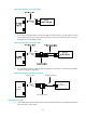
Table 7 Straight-through cable pinouts
Pinout No. A B
1 Orange/white
Orange/white
2 Orange
Orange
3 Green/white
Green/white
4 Blue
Blue
5 Blue/white
Blue/white
6 Green
Green
7 Brown/white
Brown/white
8 Brown
Brown
Table 8 Crossover cable pinouts
Pinout No. A B
1 Orange/white
Green/white
2 Orange
Green
3 Green/white
Orange/white
4 Blue
Blue
5 Blue/white
Blue/white
6 Green
Orange
7 Brown/white
Brown/white
8 Brown
Brown
NOTE:
Strictly follow the pinouts in the above tables when identifying or making the two types of Ethernet cables.
Otherwise, the communication quality might be affected.
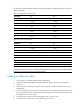
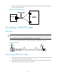
Making an Ethernet cable
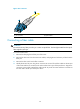
1. Cut the cable to a required length with the crimping pliers.
2. Strip off an appropriate length of the cable sheath. The length is typically that of the RJ-45
connector.
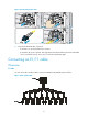
3. Untwist the pairs so that they can lay flat, and arrange the colored wires based on the wiring
specifications.
4. Cut the top of the wires even with one another. Insert the wires into the RJ-45 end and make sure
the wires extend to the front of the RJ-45 end and make good contact with the metal contacts in the
RJ-45 end and in the correct order.
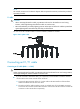
5. Crimp the RJ-45 connector with the crimping pliers until you hear a click.
6. Use a cable tester to verify the correct connectivity of the cable.