
R3303-HP HSR6800 Routers High Availability Configuration Guide


96
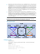
• Specify Router A as the master node of primary ring 1, GigabitEthernet 3/0/1 as the primary port
and GigabitEthernet 3/0/2 as the secondary port. Specify Router E as the master node of subring
2, GigabitEthernet 3/0/1 as the primary port and GigabitEthernet 3/0/2 as the secondary port.
Specify Router F as the master node of subring 3, GigabitEthernet 3/0/1 as the primary port and
GigabitEthernet 3/0/2 as the secondary port. Specify Router G as the master node of subring 4,
GigabitEthernet 3/0/1 as the primary port and GigabitEthernet 3/0/2 as the secondary port.
Specify Router H as the master node of subring 5, GigabitEthernet 3/0/1 as the primary port and
GigabitEthernet 3/0/2 as the secondary port.
• Specify Router A as the edge node of the connected subrings, its GigabitEthernet 3/0/3 and
GigabitEthernet 3/0/4 as the edge ports. Specify Router D as the transit node of the primary ring
and edge node of the connected subrings, its GigabitEthernet 3/0/3 and GigabitEthernet 3/0/4
as the edge ports. Specify Router B and Router C as the transit node of the primary ring and
assistant-edge nodes of the connected subrings, their GigabitEthernet 3/0/3 and GigabitEthernet
3/0/4 as the edge ports.
NOTE:
Configure the primary and secondary ports on the master nodes correctly to make sure that other
protocols still work correctly when data VLANs are denied by the secondary ports.
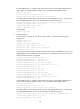
Figure 26 Network diagram
Configuration procedure
1. Configure Router A:
# Create VLANs 1 through 30, map these VLANs to MSTI 1, and activate the MST region
configuration.
<RouterA> system-view
[RouterA] vlan 1 to 30
[RouterA] stp region-configuration
[RouterA-mst-region] instance 1 vlan 1 to 30
[RouterA-mst-region] active region-configuration
[RouterA-mst-region] quit
GE3/0
/2
GE3/
0/1
GE3/
0
/1
GE3/0/
2
GE3/0/3
G
E3/
0/4
GE3/0/
4
GE3/0/3