
R3303-HP HSR6800 Routers High Availability Configuration Guide


105
Load balanced intersecting-ring configuration example
Networking requirements
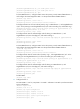
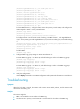
As shown in Figure 27,
• Router A, Router B, Router C, Router D, and Router F form RRPP domain 1, and VLAN 100 is the
primary control VLAN of the RRPP domain. Router A is the master node of the primary ring, Ring 1.
Router D is the transit node of Ring 1. Router F is the master node of the subring Ring 3. Router C is
the edge node of the subring Ring 3. Router B is the assistant-edge node of the subring Ring 3.
• Router A, Router B, Router C, Router D, and Router E form RRPP domain 2, and VLAN 105 is the
primary control VLAN of the RRPP domain. Router A is the master node of the primary ring, Ring 1.
Router D is the transit node of Ring 1. Router E is the master node of the subring Ring 2. Router C is
the edge node of the subring Ring 2. Router B is the assistant-edge node of the subring Ring 2.
• Specify VLAN 11 as the protected VLAN of domain 1, and VLAN 12 the protected VLAN of domain
2. You can implement VLAN-based load balancing on Ring 1.
• Because Ring 2 has the same edge node and assistant-edge node, and the two subrings have the
same SRPTs, you can add Ring 2 and Ring 3 to the RRPP ring group to reduce Edge-Hello traffic.
Figure 27 Network diagram
Configuration procedure
1. Configure Router A:
# Create VLANs 11 and 12, map VLAN 11 to MSTI 1 and VLAN 12 to MSTI 2, and activate MST
region configuration.
<RouterA> system-view
[RouterA] vlan 11 to 12
[RouterA] stp region-configuration
[RouterA-mst-region] instance 1 vlan 11
[RouterA-mst-region] instance 2 vlan 12
[RouterA-mst-region] active region-configuration