
R3303-HP HSR6800 Routers High Availability Configuration Guide


172
• Configure a track entry on Router A, Router B, and Router C to monitor their own GigabitEthernet
1/0/2. When the interface on Router A, Router B, or Router C fails, the weight of the corresponding
router decreases so that another router with a higher weight can take over.
• Configure track entries on Router C to monitor Router A and Router B. When Router A or Router B
fails, Router C immediately takes over the AVF on Router A or Router B.
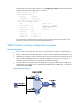
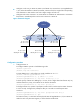
Figure 47 Network diagram
Configuration procedure
1. Configure Router A:
# Configure VRRP to operate in load balancing mode.
<RouterA> system-view
[RouterA] vrrp mode load-balance
# Create VRRP group 1 and configure its virtual IP address as 10.1.1.1.
[RouterA] interface gigabitethernet 1/0/1
[RouterA-GigabitEthernet1/0/1] ip address 10.1.1.2 24
[RouterA-GigabitEthernet1/0/1] vrrp vrid 1 virtual-ip 10.1.1.1
# Set the priority of Router A in VRRP group 1 to 120, which is higher than that of Router B (110)
and that of Router C (100), so that Router A can become the master.
[RouterA-GigabitEthernet1/0/1] vrrp vrid 1 priority 120
# Configure Router A to operate in preemptive mode so that it can become the master whenever
it works correctly. Configure the preemption delay as 5 seconds to avoid frequent status
switchover.
[RouterA-GigabitEthernet1/0/1] vrrp vrid 1 preempt-mode timer delay 5
[RouterA-GigabitEthernet1/0/1] quit
# Create track entry 1 to associate with the physical status of GigabitEthernet 1/0/2 on Router A.
When the track entry becomes negative, it means that the interface fails.
Host A Host B Host C
Router A Router B Router C
GE1/0/1
IP: 10.1.1.2/24
VIP: 10.1.1.1/24
Network
GE1/0/1
IP: 10.1.1.3/24
VIP: 10.1.1.1/24
GE1/0/1
IP: 10.1.1.4/24
VIP: 10.1.1.1/24
Master
AVF 1
Backup
AVF 2
Backup
AVF 3
IP: 10.1.1.5/24
Gateway IP: 10.1.1.1/24
IP: 10.1.1.6/24
Gateway IP: 10.1.1.1/24
IP: 10.1.1.7/24
Gateway IP: 10.1.1.1/24
GE1/0/2 GE1/0/2
GE1/0/2