
R3303-HP HSR6800 Routers High Availability Configuration Guide


207
Ste
p
Command
Remarks
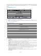
7. Configure the minimum
interval for transmitting BFD
control packets.
bfd min-transmit-interval value
Optional.
For more information, see the
description of the Desired Min TX
Interval field in "BFD packet
format."
The default setti
ng is 400
milliseconds.
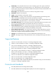
8. Configure the minimum
interval for receiving BFD
control packets.
bfd min-receive-interval value
Optional.
For more information, see the
description of the Required Min RX
Interval field in "BFD packet
format."
The default setti
ng is 400
milliseconds.
9. Configure the detection time
multiplier.
bfd detect-multiplier value
Optional.
For more information, see the
description of the Detect Mult field
in "BFD packet format."
5
by default.
In Figure 52, if you configure the Desired Min TX Interval as 100 milliseconds, Required Min RX Interval
as 300 milliseconds, and Detect Mult as 5 on Router A, and then configure the Desired Min TX Interval
as 150 milliseconds, Required Min RX Interval as 400 milliseconds, and Detect Mult as 10 on Router B:
• The actual transmitting interval on Router A is 400 milliseconds, which is the greater value between
the minimum interval for transmitting BFD control packets on Router A (100 milliseconds) and the
minimum interval for receiving BFD control packets on Router B (400 milliseconds).
• The actual transmitting interval on Router B is 300 milliseconds, which is the greater value between
the minimum interval for transmitting BFD control packets on Router B (150 milliseconds) and the
minimum interval for receiving BFD control packets on Router A (300 milliseconds).
• The actual detection time on Router A is 3000 milliseconds, which is 10 × 300 milliseconds (Detect
Mult on Router B × actual transmitting interval on Router B).
• The actual detection time on Router B is 2000 milliseconds, which is 5 × 400 milliseconds (Detect
Mult on Router A × actual transmitting interval on Router A).
The tunnel interfaces of HSR6802/HSR6804/HSR6808 support BFD. If you do not specify a tunnel
template on the tunnel interface for receiving BFD packets with the service slot slot-number command, the
active main processing unit (MPU) of the device will receive and then discard BFD packets, and the
session state remains down. To avoid such cases, HP recommends specifying a tunnel template, rather
than the active MPU, on the tunnel interface by using the service slot slot-number command.
Enabling trap
When the trap function is enabled on the BFD module, the module will generate trap messages at the
notifications level to report the important events of the module. The generated trap messages are sent to
the device's information center, which determines the output rules for the trap messages (whether to
output the trap messages and the output destinations). For the information center configuration, see
Network Management and Monitoring Configuration Guide.