
R3303-HP HSR6800 Routers High Availability Configuration Guide
236
PING 30.1.1.1: 56 data bytes, press CTRL_C to break
Reply from 30.1.1.1: bytes=56 Sequence=1 ttl=254 time=2 ms
Reply from 30.1.1.1: bytes=56 Sequence=2 ttl=254 time=1 ms
Reply from 30.1.1.1: bytes=56 Sequence=3 ttl=254 time=1 ms
Reply from 30.1.1.1: bytes=56 Sequence=4 ttl=254 time=2 ms
Reply from 30.1.1.1: bytes=56 Sequence=5 ttl=254 time=1 ms
--- 30.1.1.1 ping statistics ---
5 packet(s) transmitted
5 packet(s) received
0.00% packet loss
round-trip min/avg/max = 1/1/2 ms
# The output on Router B is similar to that on Router A. When the master route fails, the hosts in
30.1.1.0/24 can still communicate with the hosts in 20.1.1.0/24.
[RouterB] ping -a 30.1.1.1 20.1.1.1
PING 20.1.1.1: 56 data bytes, press CTRL_C to break
Reply from 20.1.1.1: bytes=56 Sequence=1 ttl=254 time=2 ms
Reply from 20.1.1.1: bytes=56 Sequence=2 ttl=254 time=1 ms
Reply from 20.1.1.1: bytes=56 Sequence=3 ttl=254 time=1 ms
Reply from 20.1.1.1: bytes=56 Sequence=4 ttl=254 time=1 ms
Reply from 20.1.1.1: bytes=56 Sequence=5 ttl=254 time=1 ms
--- 20.1.1.1 ping statistics ---
5 packet(s) transmitted
5 packet(s) received
0.00% packet loss
round-trip min/avg/max = 1/1/2 ms
VRRP-track-interface management collaboration configuration
example
In this example, the master monitors the uplink interface.
Network requirements
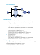
As shown in Figure 61, Host A needs to access Host B on the Internet. The default gateway of Host A is
10 .1.1.10 / 2 4 .
Router A and Router B belong to VRRP group 1, whose virtual IP address is 10.1.1.10.
When Router A works correctly, packets from Host A to Host B are forwarded through Router A. When
VRRP detects that a fault is on the uplink interface of Router A through the interface management module,
packets from Host A to Host B are forwarded through Router B.