
R3303-HP HSR6800 Routers High Availability Configuration Guide


28
Task Command
Remarks
Display LTR information received
by a MEP.
display cfd linktrace-reply [ service-instance
instance-id [ mep mep-id ] ] [ | { begin |
exclude | include } regular-expression ]
Available in any view.
Display the information of a remote
MEP.
display cfd remote-mep service-instance
instance-id mep mep-id [ | { begin | exclude
| include } regular-expression ]
Available in any view.
Display the content of the LTR
messages received as responses to
the automatically sent LTMs.
display cfd linktrace-reply auto-detection
[ size size-value ] [ | { begin | exclude |
include } regular-expression ]
Available in any view.
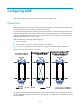
CFD configuration example
Network requirements
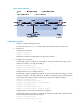
As shown in Figure 6:
• The network comprises five devices and is divided into two MDs: MD_A (level 5) and MD_B (level
3). All ports belong to VLAN 100, and the MAs in the two MDs all serve VLAN 100. Assume that
the MAC addresses of Router A through Router E are 0010-FC00-6511, 0010 -FC00 -6512,
0010 -FC00 -6513, 0010 -FC00 -6514, and 0010 -FC00 -6515, respectively.
• MD_A has three edge ports: GigabitEthernet 3/0/1 on Router A, GigabitEthernet 3/0/3 on
Router D, and GigabitEthernet 3/0/4 on Router E. They are all inward-facing MEPs. MD_B has two
edge ports: GigabitEthernet 3/0/3 on Router B and GigabitEthernet 3/0/1 on Router D. They are
both outward-facing MEPs.
• In MD_A, Router B is designed to have MIPs when its port is configured with low level MEPs. Port
GigabitEthernet 3/0/3 is configured with MEPs of MD_B, and the MIPs of MD_A can be
configured on this port. Configure the MIP generation rule of MD_A as explicit.
• The MIPs of MD_B are designed on Router C, and are configured on all ports. You should configure
the MIP generation rule as default.
• Configure CC to monitor the connectivity among all the MEPs in MD_A and MD_B. Configure LB to
locate link faults.
• After the status information of the entire network is obtained, use LT to detect link faults.