
R3303-HP HSR6800 Routers High Availability Configuration Guide


56
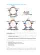
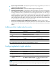
Figure 14 Schematic diagram before and after protection switchover
As shown in Figure 14, traffic travels from station D to station B along Ringlet 0. The transmission path is
station D—station E—station A—station B. After the span between station A and station E fails, a
protection switchover occurs.
• In wrapping mode, traffic that should originally travel from station E to A along Ringlet 0 is directed
to Ringlet 1 to reach station A. The new transmission path is station D—station E—station D—station
C—station B—station A—station B.
• In steering mode, traffic that should have traveled from station D to station B along Ringlet 0 is
steered to Ringlet 1 for transmission. The new transmission path is Station D—Station C—Station B.
RPR protection switching uses the following protection hierarchy listed in the order of decreasing severity:
• Forced switch (FS)
• Signal fail (SF), related to current physical status.
• Signal degrade (SD), related to current physical status.
• Manual switch (MS)
• Wait to restore (WTR)
• Idle
Protection switching occurs only when requested by a station on the ring. The hierarchy of protection
requests is the same as this protection switching hierarchy. Among protection requests, FS and MS