
R3303-HP HSR6800 Routers High Availability Configuration Guide


69
Task Command
Remarks
Display VRRP standby group
information of RPR.
display rpr vrrp-info [ rpr
interface-number ] [ | { begin |
exclude | include }
regular-expression ]
Available in any view.
Clear the statistics about protection
events on the RPR station.
reset rpr protection statistics [ rpr
interface-number ]
Available in user view.
Clear the statistics of the specified
RPR physical ports.
reset counters interface [ rprpos
[ interface-number ] ]
Available in user view.
Clear the statistics of the specified
RPR logical interfaces.
reset counters interface [ rpr
[ interface-number ] ]
Available in user view.
RPR configuration examples
RPR interface binding configuration example
Network requirements
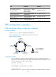
As shown in Figure 15, stations A through E form an RPR ring.
Bind the RPR physical ports to the RPR logical interface on each station.
Figure 15 Network diagram
Configuration procedure
1. Create an RPR logical interface and bind two RPR physical ports to the RPR logical interface:
# On Station A, create RPR logical interface RPR1, and bind RPR physical ports RPRPOS 1/1 (the
west port) and RPRPOS 1/2 (the east port) to RPR 1.
<StationA> system-view
[StationA] interface rpr 1
[StationA-RPR1] rpr bind rprpos 1/1 ringlet0
[StationA-RPR1] rpr bind rprpos 1/2 ringlet1
[StationA-RPR1] quit
Configure Station B, C, D, and E in the same way Station A is configured. (Details not shown.)
Station E
000F- E257-0005
Station D
000F-E257- 0004
Station C
000F- E257-0003
Station B
000F-E257-0002
Station A
000F-E257- 0001
Ringlet 1
Ringlet 0
East port (RPRPOS1/2)
West port (RPRPOS1/1)