
R3303-HP HSR6800 Routers High Availability Configuration Guide


80
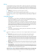
1. Such configurations enable the ring to block different links based on VLANs and achieve single-ring
load balancing.
Figure 22 Schematic diagram for a single-ring load balancing network
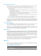
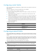
Intersecting-ring load balancing
In an intersecting-ring network, you can also achieve load balancing by configuring multiple domains.
As shown in Figure 23, R
ing 1 is the primary ring and Ring 2 is the subring in both Domain 1 and
Domain 2. Domain 1 and Domain 2 are configured with different protected VLANs. Device A is
configured as the master node of Ring 1 in Domain 1. Device D is configured as the master node of Ring
1 in Domain 2. Device E is configured as the master node of Ring 2 in both Domain 1 and Domain 2.
However, different ports on Device E are blocked in Domain 1 and Domain 2. With the configurations,
you can enable traffic from different VLANs to travel over different paths in the subring and primary ring,
achieving intersecting-ring load balancing.
Figure 23 Schematic diagram for an intersecting-ring load balancing network
Protocols and standards
RFC 3619, Extreme Networks' Ethernet Automatic Protection Switching (EAPS) Version 1 is related to
RRPP.
Device A Device B
Device CDevice D
Domain 1
Ring 1
Domain 2
Device A
Device B
Device C
Device D
Device E
Ring 1
Ring 2
Domain 1
Domain 2