
R3303-HP HSR6800 Routers High Availability Configuration Guide


91
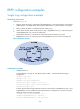
Figure 25 Network diagram
Configuration procedure
1. Configure Router A:
# Create VLANs 1 through 30, map these VLANs to MSTI 1, and activate the MST region
configuration.
<RouterA> system-view
[RouterA] vlan 1 to 30
[RouterA] stp region-configuration
[RouterA-mst-region] instance 1 vlan 1 to 30
[RouterA-mst-region] active region-configuration
[RouterA-mst-region] quit
# Set the physical state change suppression interval to 0 seconds on GigabitEthernet 3/0/1 and
GigabitEthernet 3/0/2. Disable the spanning tree feature, configure the two ports as trunk ports,
and assign them to VLANs 1 through 30.
[RouterA] interface gigabitethernet 3/0/1
[RouterA-GigabitEthernet3/0/1] link-delay 0
[RouterA-GigabitEthernet3/0/1] undo stp enable
[RouterA-GigabitEthernet3/0/1] port link-type trunk
[RouterA-GigabitEthernet3/0/1] port trunk permit vlan 1 to 30
[RouterA-GigabitEthernet3/0/1] quit
[RouterA] interface gigabitethernet 3/0/2
[RouterA-GigabitEthernet3/0/2] link-delay 0
[RouterA-GigabitEthernet3/0/2] undo stp enable
[RouterA-GigabitEthernet3/0/2] port link-type trunk
[RouterA-GigabitEthernet3/0/2] port trunk permit vlan 1 to 30
[RouterA-GigabitEthernet3/0/2] quit
# Create RRPP domain 1, configure VLAN 4092 as the primary control VLAN of RRPP domain 1,
and configure the VLANs mapped to MSTI 1 as the protected VLANs of RRPP domain 1.
[RouterA] rrpp domain 1
[RouterA-rrpp-domain1] control-vlan 4092
[RouterA-rrpp-domain1] protected-vlan reference-instance 1
# Configure Router A as the master node of primary ring 1, with GigabitEthernet 3/0/1 as the
primary port and GigabitEthernet 3/0/2 as the secondary port, and enable ring 1.