
R3303-HP HSR6800 Routers Network Management and Monitoring Configuration Guide


114
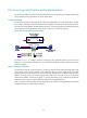
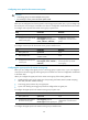
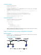
Figure 45 Layer 2 remote port mirroring implementation
As shown in Figure 45, the source device copies packets received on the source port Ethernet 1/1 to the
egress port Ethernet 1/2. The egress port forwards the packets to the intermediate devices, which then
broadcast the packets in the remote probe VLAN and transmit the packets to the destination device.
Upon receiving the mirrored packets, the destination device checks whether their VLAN IDs are the same
as the remote probe VLAN ID. If yes, the device forwards the packets to the data monitoring device
through the monitor port Ethernet 1/2.
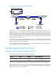
To make sure the source device and the destination device can communicate at Layer 2 through the
remote probe VLAN, assign the intermediate devices' ports along the path between the source and
destination devices to the remote probe VLAN.
To monitor both the received and sent packets of a port in a remote mirroring group, you must make some
special configurations on the intermediate devices.
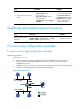
Configuring local port mirroring
Local port mirroring configuration task list
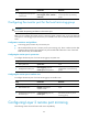
The following matrix shows the feature and router compatibility:
Feature 6602 HSR6602 6604/6608/6616
Local port mirroring Yes
Yes only on fixed
interfaces
Yes only when SAP modules are
operating in bridge mode
Local port mirroring takes effect only when the source ports and the monitor port are configured.
A port can belong to only one mirroring group. However, on devices that support mirroring groups with
multiple monitor ports, a port can serve as a source port for multiple mirroring groups, but cannot be an
egress port or monitor port at the same time.