
R3303-HP HSR6800 Routers Network Management and Monitoring Configuration Guide
72
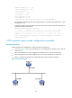
# Configure Router B to operate in broadcast client mode and receive broadcast messages on
GigabitEthernet 2/0/1.
<RouterB> system-view
[RouterB] interface gigabitethernet 2/0/1
[RouterB-GigabitEthernet2/0/1] ntp-service broadcast-client
Router A and Router B get synchronized upon receiving a broadcast message from Router C.
# Take Router A as an example. Display the NTP status of Router A after clock synchronization.
[RouterA-GigabitEthernet2/0/1] display ntp-service status
Clock status: synchronized
Clock stratum: 3
Reference clock ID: 3.0.1.31
Nominal frequency: 64.0000 Hz
Actual frequency: 64.0000 Hz
Clock precision: 2^7
Clock offset: 0.0000 ms
Root delay: 31.00 ms
Root dispersion: 8.31 ms
Peer dispersion: 34.30 ms
Reference time: 16:01:51.713 UTC Sep 19 2005 (C6D95F6F.B6872B02)
The output shows that Router A has synchronized to Router C. The stratum level of Router A is 3,
and that of Router C is 2.
# Display the NTP session information of Router A, which shows that an association has been set
up between Router A and Router C.
[RouterA-GigabitEthernet2/0/1] display ntp-service sessions
source reference stra reach poll now offset delay disper
**************************************************************************
[1234] 3.0.1.31 127.127.1.0 2 254 64 62 -16.0 32.0 16.6
note: 1 source(master),2 source(peer),3 selected,4 candidate,5 configured
Total associations : 1
NTP multicast mode configuration example
Network requirements
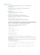
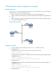
As shown in Figure 29, Router C functions as the NTP server for multiple devices on different network
segments and synchronizes the time among multiple devices.
• Router C’s local clock is to be used as a reference source, with the stratum level 2.
• Router C operates in multicast server mode and sends multicast messages from GigabitEthernet
2/0/1.
• Router D and Router A operate in multicast client mode and receive multicast messages through
their respective GigabitEthernet 2/0/1.