
R3303-HP HSR6800 Routers Network Management and Monitoring Configuration Guide

77
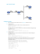
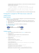
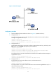
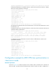
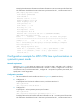
Figure 31 Network diagram
Configuration procedure
1. Set the IP address for each interface as shown in Figure 31. (Details not shown.)
2. Configure Router A:
# Configure Router A to operate in NTP broadcast client mode and receive NTP broadcast
messages on GigabitEthernet 2/0/1.
<RouterA> system-view
[RouterA] interface gigabitethernet 2/0/1
[RouterA-GigabitEthernet2/0/1] ntp-service broadcast-client
3. Configure Router B:
# Enable NTP authentication on Router B. Configure an NTP authentication key, with the key ID of
88 and key value of 123456. Specify the key as a trusted key.
<RouterB> system-view
[RouterB] ntp-service authentication enable
[RouterB] ntp-service authentication-keyid 88 authentication-mode md5 123456
[RouterB] ntp-service reliable authentication-keyid 88
# Configure Router B to operate in broadcast client mode and receive NTP broadcast messages on
GigabitEthernet 2/0/1.
[RouterB] interface gigabitethernet 2/0/1
[RouterB-GigabitEthernet2/0/1] ntp-service broadcast-client
4. Configure Router C:
# Specify the local clock as the reference source, with the stratum level 3.
<RouterC> system-view
[RouterC] ntp-service refclock-master 3
# Configure Router C to operate in NTP broadcast server mode and use GigabitEthernet 2/0/1 to
send NTP broadcast packets.
[RouterC] interface gigabitethernet 2/0/1
[RouterC-GigabitEthernet2/0/1] ntp-service broadcast-server