HP IBRIX X9000 Network Storage System Installation Guide Abstract This document describes how to install the X9000 File Serving Software. It is intended for HP Services personnel who configure X9000 series Network Storage systems at customer sites. For upgrade information, see the administration guide for your system. For the latest X9000 guides, browse to http://www.hp.com/support/manuals.
© Copyright 2009, 2012 Hewlett-Packard Development Company, L.P. Confidential computer software. Valid license from HP required for possession, use or copying. Consistent with FAR 12.211 and 12.212, Commercial Computer Software, Computer Software Documentation, and Technical Data for Commercial Items are licensed to the U.S. Government under vendor's standard commercial license. The information contained herein is subject to change without notice.
Contents 1 Installing X9300 and X9320 systems.............................................................6 Network information.................................................................................................................6 Installation checklist..................................................................................................................6 Installing the latest IBRIX X9000 software release..........................................................................
Configuring automated failover................................................................................................81 Example configuration.............................................................................................................81 Specifying VIFs in the client configuration...................................................................................82 Configuring link state monitoring for iSCSI network interfaces.......................................................
Troubleshooting the InfiniBand network....................................................................................145 Enabling client access...........................................................................................................146 Setting up Voltaire InfiniBand ................................................................................................146 12 Support and other resources...................................................................148 Contacting HP.......
1 Installing X9300 and X9320 systems The system is configured at the factory as follows: • X9000 File Serving Software 6.
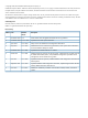
Step Task More information 5. Perform the installation “Starting the installation and configuration” (page 8) 6. Set up IBRIX virtual IP addresses for client access “Configuring virtual interfaces for client access” (page 80) 7.
4491+0 records out 4709154816 bytes (4.7 GB) copied, 957.784 seconds, 4.9 MB/s 5. 6. 7. Insert the USB key into the server to be installed. Restart the server to boot from the USB key. (Press F11 and use option 3 ). When the “HP Network Storage System” screen appears, enter qr to install the software. Repeat steps 5–8 on each server and then go to the next section, “Starting the installation and configuration.” Starting the installation and configuration Complete the following steps: 1.
• The default gateway provides a route between networks. If your default gateway is on a different subnet than bond0, skip this field. Later in this procedure, you can select either Web UI or ASCII text mode to complete the installation. A gateway address is required to use the Web UI. • VLAN capabilities provide hardware support for running multiple logical networks over the same physical networking hardware. IBRIX supports the ability to associate a VLAN tag with a FSN interface.
5. Select a method to complete the installation: • Web UI over the network from a remote system. The URL for the IBRIX Getting Started Wizard is displayed on the console when you select this option. • A local Web UI session on this console. Selecting this option launches the IBRIX Getting Started Wizard from a web browser on this console. • ASCII text mode. This is a continuation of the menus you have been using.
Completing the installation in text mode — unified network To configure the first server, complete the following steps: 1. On the Form a Cluster — Step 2 dialog box, enter a name for the cluster and specify the IP address and netmask for the Management Console IP (also called the Cluster Management IP). This a virtual IP address (VIF) assigned to the entire cluster for management use. Think of it as the “IP address of the cluster.” You should connect to this VIF in future GUI management sessions.
3. The Configuration Summary lists the configuration you have specified. Select Commit to continue. 4. The wizard now configures the active management console (Fusion Manager) on the server.
5. Optionally, create a template to configure the remaining nodes. To use the template, all nodes must have identical network configurations. If you are using separate cluster/user networks, or the node configurations will not be identical, select Exit. In the hostname templates, the parameters enclosed in braces ({...}) expand in the following manner: • number num: The number of file serving nodes in the cluster.
A configuration script now performs some tuning and imports the LUNs into the X9000 software. When the script is complete, you can install the remaining servers. If you did not create a template, go to the next section. If you created a template, go to “Installing additional servers using the template” (page 17). Installing additional servers without the template Complete the following steps: 1. Using a console connection, log into the server you are installing.
4. 5. 6. The Verify Configuration dialog box shows the configuration for the server. Select Commit to continue. On the Form a Cluster — Step 2 dialog box, enter the cluster name and specify the IP address and netmask for the Management Console IP (also called the Cluster Management IP). Also enter the IP addresses and domain for your DNS servers, and the IP addresses for your NTP servers. The Network Configuration dialog box lists the Ethernet devices included in bond0.
7. The Configuration Summary dialog box lists the configuration you specified. Select Commit to apply the configuration. 8. The wizard registers a passive Fusion Manager on the server, and then configures and starts it. The installation is complete.
Installing additional servers using the template Complete the following steps: 1. Using a console connection, log into the server you are installing. The Set IP or Discover FMs dialog box appears. Select Discover Existing Clusters to join them from this console. 2. The installation wizard scans the network for existing clusters and lists the clusters on the Join Cluster dialog box. Select the appropriate Fusion Manager management console. 3.
4. The Verify Configuration dialog box shows the configuration for the server. If the configuration is correct, select Accept and go to step 4. NOTE: To change the configuration, select Reject, and the following screen appears. Choose Select FM Again to reselect the Fusion Manager and use the template again. To configure the server manually, select Enter FM IP and use the procedure corresponding to your network type.
5. The wizard registers a passive Fusion Manager on the server, and then configures and starts it. The installation is complete. Completing the installation in text mode — separate cluster and user networks To configure the first server, complete the following steps: 1. On the Form a Cluster — Step 2 dialog box, enter a name for the cluster and specify the IP address and netmask for the Management Console IP (also called the Cluster Management IP).
On the Edit Bonded Interface dialog box, enter the IP address and netmask and specify any bond options. The slaves are selected by the system based on the following preference: • 10G dual port PCI add-on card • 1G quad port PCI add-on card • Embedded server network ports Change the slave devices as necessary for your configuration. When you select Ok, the Configuration Summary dialog box appears. Select Back and return to the Network Configuration dialog box. 3. 20 Set up bond1.
On the Select Interface Type dialog box, select Ok to create a bonded interface. On the Add Bonded Interface dialog box, enter bond1 as the name for the interface. Also specify the appropriate options and slave devices. Use mode 6 bonding for a 1GbE network, and mode 1 bonding for a 10GbE network.
When you select Ok, the Configure Network dialog box reappears. Select bond1, and then select Configure. The Edit Bonded Interface dialog box is displayed. Enter the IP address and netmask for bond1 and select Ok. 22 4. The Configuration Summary lists the configuration you have specified. Select Commit to continue. 5. The wizard now configures the active management console (Fusion Manager) on the server. 6. The template does not apply when configuring separate cluster and user networks. Select Exit.
A configuration script now performs some tuning and imports the LUNs into the X9000 software. 7. If the bond0/cluster network is not routed and the bond1/user network is routed, complete the following steps to define the default gateway for bond1: • Set the default gateway in /etc/sysconfig/network. • Add a default route for bond1: ibrix_nic -r -n IFNAME -h HOSTNAME -A -R ROUTE For example: # ibrix_nic -r -n bond1 -h ibrix02a -A -R 10.10.125.1 8.
3. The installation wizard scans the network for existing clusters and lists the clusters on the Join Cluster dialog box. Select the appropriate cluster. 4. The Verify Hostname dialog box lists a hostname generated from the management console. Accept or change this hostname.
5. The Verify Configuration dialog box shows the configuration for the server. Because you need to change the configuration, select Reject, and the following screen appears. Select Enter FM IP. 6. On the System Date and Time dialog box, enter the system date (day/month/year) and time (24-hour format). Tab to the Time Zone field and press Enter to display a list of time zones. Select your time zone from the list.
7. The Server Networking Configuration dialog box defines the server on bond0. Note the following: • The hostname can include alphanumeric characters and the hyphen (–) special character. It is a best practice to use only lowercase characters in hostnames; uppercase characters can cause issues with IBRIX software. Do not use an underscore (_) in the hostname. • The IP address is the address of the server on bond0. • The default gateway provides a route between networks.
9. On the Join a Cluster – Step 2 dialog box, enter the requested information. NOTE: Register IP is the Fusion Manager (management console) IP, not the IP you are registering for this server. 10. The Network Configuration dialog box lists the Ethernet devices in bond0. If the devices are correct, go to the next step. If the devices are not correct, select bond0 and then select Configure to customize the interface.
On the Edit Bonded Interface dialog box, enter the IP address and netmask, specify any bond options, and change the slave devices as necessary for your configuration. When you select Ok, the Configuration Summary dialog box appears. Select Back and return to the Network Configuration dialog box. 11. Configure bond1. Select from the Network Configuration dialog box.
On the Select Interface Type dialog box, select Ok to create a bonded interface. On the Add Bonded Interface dialog box, enter bond1 as the name for the interface. Also specify the appropriate options and slave devices. Use mode 6 bonding for a 1GbE network, and mode 1 bonding for a 10GbE network.
When you select Ok, the Configure Network dialog box reappears. Select bond1, and then select Configure. The Edit Bonded Interface dialog box is displayed. Enter the IP address and netmask for bond1, specify any bond options, and change the slave devices if necessary. 12. The Configuration Summary dialog box lists the configuration you specified. Select Commit to apply the configuration. 13. The wizard registers a passive Fusion Manager on the server, and then configures and starts it. 14.
2 Configuring the cluster with the Getting Started Wizard (X9300/X9320 systems) The Getting Started Wizard configures the cluster in a few steps. Be sure to have the necessary IP addresses available. NOTE: This wizard can be used only for X9300 and X9320 systems. Running the wizard The Cluster Settings page asks for information to identify your cluster. Enter a name for the cluster and specify the Cluster Management IP address.
To update your license keys, click Update. Typically, you will need a license key for each server. Download your licenses from the HP website and place them in a location that can be accessed by this server. Use Browse to locate a license key and then click Add. Repeat this step for each license key. Enter the DNS server addresses and search domain for your cluster. Also enter your NTP server addresses.
The wizard attempts to access the addresses that you specify. If it cannot reach an address, a message such as Primary DNS Server Unreachable will be displayed on the screen. The File Servers page lists all servers the wizard found on your network. If the list includes servers that do not belong in the cluster, select those servers and click Remove. If a server is not defined, select the server and click Configure.
To configure a server, select the server on the File Servers page and click Configure. Enter the host name and IP address of the server. If the wizard can locate the subnet masks and iLO IP address, it will fill in those values. If your cluster should include servers that were not listed on the File Servers page, configure an IP address manually on the servers, using their local console setup screens. Then click Add on the File Servers page to add the servers to the cluster.
f you create a CIFS share, you will need to configure the file serving nodes for CIFS and configure authentication. You might also want to set certain CIFS parameters such as user permissions. Other configuration options are also available for NFS shares. See the HP IBRIX X9000 Network Storage System File System User Guide for more information. The Summary lists any warnings or other items noted during the post-installation checks. Click the items to determine whether further action is needed.
The wizard saves an installation log at /usr/local/ibrix/log/installtime.log on the server where you ran the wizard. Click View Log to display the log. When you click Finish to exit the wizard, the Fusion Manager is restarted. When the service is running again, you can log into the GUI. Troubleshooting the Getting Started Wizard If you are unable to resolve an issue, contact HP support for assistance.
Troubleshooting steps: 1. Relaunch the wizard, go to the Cluster Settings page, and click Next to retry the operation. If the operation fails again, run ifconfig bond0:0. If the output is empty, use the following command to set the VIF on the server: ibrix_fm -c -d bond0:0 -n -v cluster 2.
Troubleshooting steps: 1. Relaunch the wizard, go to the Cluster Settings page, and click Next to retry the operation. If the operation fails again, run ifconfig bond0:0. If the output is empty, use the following command to set the VIF on the server: ibrix_fm -c -d bond0:0 -n -v cluster 2.
Troubleshooting steps: 1. Relaunch the wizard, go to the Cluster Settings page, and click Next to retry the operation. If the operation fails again, run ifconfig bond0:0. If the output is empty, use the following command to set the VIF on the server: ibrix_fm -c -d bond0:0 -n -v cluster 2.
Troubleshooting steps: 1. Relaunch the wizard, go to the Cluster Settings page, and click Next to retry the operation. If the operation fails again, run ifconfig bond0:0. If the output is empty, use the following command to set the VIF on the server: ibrix_fm -c -d bond0:0 -n -v cluster 2.
Troubleshooting steps: 1. Relaunch the wizard, go to the Cluster Settings page, and click Next to retry the operation. If the operation fails again, run ifconfig bond0:0. If the output is empty, use the following command to set the VIF on the server: ibrix_fm -c -d bond0:0 -n -v cluster 2.
Troubleshooting steps: 1. Relaunch the wizard, go to the Cluster Settings page, and click Next to retry the operation. If the operation fails again, run ifconfig bond0:0. If the output is empty, use the following command to set the VIF on the server: ibrix_fm -c -d bond0:0 -n -v cluster 2.
Troubleshooting steps: 1. Relaunch the wizard, go to the Cluster Settings page, and click Next to retry the operation. If the operation fails again, run ifconfig bond0:0. If the output is empty, use the following command to set the VIF on the server: ibrix_fm -c -d bond0:0 -n -v cluster 2.
Troubleshooting steps: 1. Relaunch the wizard, go to the Cluster Settings page, and click Next to retry the operation. If the operation fails again, run ifconfig bond0:0. If the output is empty, use the following command to set the VIF on the server: ibrix_fm -c -d bond0:0 -n -v cluster 2.
Troubleshooting steps: 1. Relaunch the wizard, go to the Cluster Settings page, and click Next to retry the operation. If the operation fails again, run ifconfig bond0:0. If the output is empty, use the following command to set the VIF on the server: ibrix_fm -c -d bond0:0 -n -v cluster 2.
Troubleshooting steps: 1. Relaunch the wizard, go to the Cluster Settings page, and click Next to retry the operation. If the operation fails again, run ifconfig bond0:0. If the output is empty, use the following command to set the VIF on the server: ibrix_fm -c -d bond0:0 -n -v cluster 2.
Troubleshooting steps: 1. Relaunch the wizard, go to the Cluster Settings page, and click Next to retry the operation. If the operation fails again, run ifconfig bond0:0. If the output is empty, use the following command to set the VIF on the server: ibrix_fm -c -d bond0:0 -n -v cluster 2.
Troubleshooting steps: 1. Relaunch the wizard, go to the Cluster Settings page, and click Next to retry the operation. If the operation fails again, run ifconfig bond0:0. If the output is empty, use the following command to set the VIF on the server: ibrix_fm -c -d bond0:0 -n -v cluster 2.
Troubleshooting steps: 1. Relaunch the wizard, go to the Cluster Settings page, and click Next to retry the operation. If the operation fails again, run ifconfig bond0:0. If the output is empty, use the following command to set the VIF on the server: ibrix_fm -c -d bond0:0 -n -v cluster 2.
Troubleshooting steps: 1. Relaunch the wizard, go to the Cluster Settings page, and click Next to retry the operation. If the operation fails again, run ifconfig bond0:0. If the output is empty, use the following command to set the VIF on the server: ibrix_fm -c -d bond0:0 -n -v cluster 2.
Troubleshooting steps: 1. Relaunch the wizard, go to the Cluster Settings page, and click Next to retry the operation. If the operation fails again, run ifconfig bond0:0. If the output is empty, use the following command to set the VIF on the server: ibrix_fm -c -d bond0:0 -n -v cluster 2.
Troubleshooting steps: 1. Relaunch the wizard, go to the Cluster Settings page, and click Next to retry the operation. If the operation fails again, run ifconfig bond0:0. If the output is empty, use the following command to set the VIF on the server: ibrix_fm -c -d bond0:0 -n -v cluster 2.
Troubleshooting steps: 1. Relaunch the wizard, go to the Cluster Settings page, and click Next to retry the operation. If the operation fails again, run ifconfig bond0:0. If the output is empty, use the following command to set the VIF on the server: ibrix_fm -c -d bond0:0 -n -v cluster 2.
Troubleshooting steps: 1. Relaunch the wizard, go to the Cluster Settings page, and click Next to retry the operation. If the operation fails again, run ifconfig bond0:0. If the output is empty, use the following command to set the VIF on the server: ibrix_fm -c -d bond0:0 -n -v cluster 2.
Troubleshooting steps: 1. Relaunch the wizard, go to the Cluster Settings page, and click Next to retry the operation. If the operation fails again, run ifconfig bond0:0. If the output is empty, use the following command to set the VIF on the server: ibrix_fm -c -d bond0:0 -n -v cluster 2.
Troubleshooting steps: 1. Relaunch the wizard, go to the Cluster Settings page, and click Next to retry the operation. If the operation fails again, run ifconfig bond0:0. If the output is empty, use the following command to set the VIF on the server: ibrix_fm -c -d bond0:0 -n -v cluster 2.
Troubleshooting steps: 1. Relaunch the wizard, go to the Cluster Settings page, and click Next to retry the operation. If the operation fails again, run ifconfig bond0:0. If the output is empty, use the following command to set the VIF on the server: ibrix_fm -c -d bond0:0 -n -v cluster 2.
Troubleshooting steps: 1. Relaunch the wizard, go to the Cluster Settings page, and click Next to retry the operation. If the operation fails again, run ifconfig bond0:0. If the output is empty, use the following command to set the VIF on the server: ibrix_fm -c -d bond0:0 -n -v cluster 2.
Troubleshooting steps: 1. Relaunch the wizard, go to the Cluster Settings page, and click Next to retry the operation. If the operation fails again, run ifconfig bond0:0. If the output is empty, use the following command to set the VIF on the server: ibrix_fm -c -d bond0:0 -n -v cluster 2.
Troubleshooting steps: 1. Relaunch the wizard, go to the Cluster Settings page, and click Next to retry the operation. If the operation fails again, run ifconfig bond0:0. If the output is empty, use the following command to set the VIF on the server: ibrix_fm -c -d bond0:0 -n -v cluster 2.
Troubleshooting steps: 1. Relaunch the wizard, go to the Cluster Settings page, and click Next to retry the operation. If the operation fails again, run ifconfig bond0:0. If the output is empty, use the following command to set the VIF on the server: ibrix_fm -c -d bond0:0 -n -v cluster 2.
Troubleshooting steps: 1. Relaunch the wizard, go to the Cluster Settings page, and click Next to retry the operation. If the operation fails again, run ifconfig bond0:0. If the output is empty, use the following command to set the VIF on the server: ibrix_fm -c -d bond0:0 -n -v cluster 2.
Installing additional X9730 blades Use this procedure to install blades 2–16 on an X9730 system. Complete the following procedure on each blade: 1. Log into the blade. 2. The X9730 Setup dialog box is displayed. 3. The wizard verifies the firmware on the system and notifies you if a firmware update is needed. IMPORTANT: HP recommends that you update the firmware before continuing with the installation. X9730 systems have been tested with specific firmware recipes.
4. The wizard scans the network for existing clusters. On the Join Cluster dialog box, select the management console (Fusion Manager) for your cluster. You have several options at this point: • Use the template to configure the blade. Select Ok, and go to “Configure the blade with the template” (page 64). • Configure the blade manually.
1. The blade you are installing is assigned the appropriate name from the template, plus the last octet IP for a hostname. If necessary, you can change the hostname on the Verify Hostname dialog box. 2. The Verify Configuration dialog box shows the configuration for this blade. If the configuration is correct, select Accept and go to step 3. NOTE: To change the configuration, select Reject, and the following screen appears.
3. The installer now obtains OA/VC information from the chassis. If the installer cannot obtain the information programmatically, the following screen will appear and you will need to enter the OA/VC credentials manually. 4. The wizard now takes the following actions: 5.
6. The Network Configuration dialog box lists the interfaces configured on bond0. The configuration is complete. Select Continue. 7. The Configuration Summary dialog box lists the configuration you specified. Select Commit to apply the configuration.
NOTE: 8. Ensure that the Management IP is on the same subnet as the cluster network (bond0). The wizard registers and starts a passive management console on the blade. The installation is complete. Configure the blade manually Complete the following steps: 1. On the System Date and Time dialog box, enter the system date (day/month/year) and time (24-hour format). Tab to the Time Zone field and press Enter to display a list of time zones. Then select your time zone from the list.
2. On the Server Networking Configuration dialog box, configure this server for bond0, the cluster network. Note the following: • The hostname can include alphanumeric characters and the hyphen (–) special character. It is a best practice to use only lowercase characters in hostnames; uppercase characters can cause issues with IBRIX software. Do not use an underscore (_) in the hostname. • The IP address is the address of the server on bond0. • The default gateway provides a route between networks.
5. 6.
• If you are using the unified network layout, bond0 is already set up. Select Continue and go to step 8. • If you are using a different network layout, the necessary bonds appear on the Network Configuration screen with the correct eth devices assigned, but you need to configure the IP addresses for those bonds. Select a bond and then select Configure. On the Edit Bonded Interface dialog box, enter the IP address and netmask and specify any bond options. 8.
NOTE: Ensure that the Management IP is on the same subnet as the cluster network (bond0) for the unified network layout; bond1 for all other layouts). 9. The wizard registers and starts a passive management console on the blade. The installation is complete. Firmware updates If a firmware check determines that firmware needs to be updated, you will see a dialog box such as the following. Select Update to perform the update.
If the firmware check determines that firmware should be downgraded, you will see a dialog box such as the following. You cannot downgrade the firmware during the installation. Select Skip and then downgrade the firmware when the installation is complete. Chassis component firmware can be flashed only from blade 1. When installing blade 2 and any remaining blades, you may see the following dialog box if you are running the GUI from a blade other than blade 1.
Troubleshooting Install software cannot ping the OA This condition can occur if OA2 becomes the Active OA. Configure the OA as follows to resolve this condition: 1. From the Main Menu of the Insight Display, navigate to Enclosure Settings and press OK. 74 2. On the Enclosure Settings screen, select Active OA and press OK. 3. On the Network Settings: OA1 Active screen, select Network Properties and press OK.
4. On the Change OA Network Properties screen, set Enclosure IP to Enable and press OK to Accept. 5. On the Network Settings: OA1 Active screen, select Accept All and press OK. 6. 7. 8. 9. On the Enclosure Settings screen, select Standby OA and press OK. On the Network Settings:OA2 screen, navigate to Active IPv4 and press OK. Set the IP address, subnet mask, and gateway (optional) and Accept the changes. On the Network Settings:OA2 screen, navigate to Accept All and press OK.
3. 4. 5. Unassign the blade's profile. Reassign the blade's profile. Reboot the blade, and continue the installation. Credential Manager initialization failed If the default username or password is changed or the IP address of the OA is changed, the step to initialize the Credential Manager will fail. To initialize the Credential Manager from the command line, complete the appropriate procedure. OA and VC have the same username and password. 1.
4 Post-installation tasks Updating license keys Typically you need a license key for each server. If you did not update your license keys during the installation, download the license keys and install them as described in the administrator guide for your system. Configuring and Enabling High Availability X9730 systems The installation process configures the servers for High Availability; however, HA is disabled.
X9000 software manpages X9000 software provides manpages for most X9000 software commands. To view the manpages, set the MANPATH variable on the management console to include the path to the manpages and then export it. The manpages are in the $IBRIXHOME/man directory. For example, if $IBRIXHOME is /usr/local/ibrix, the default, you would set the MANPATH variable as follows and then export the variable.
Configuring CIFS shares (optional) NOTE: Before attempting to configure CIFS, ensure that the DNS entries for the user network IP addresses have PTR (reverse lookup) records configured. When setting up CIFS, you will need to configure user authentication and then create CIFS shares.
5 Configuring virtual interfaces for client access X9000 Software uses a cluster network interface to carry Fusion Manager traffic and traffic between file serving nodes. This network is configured as bond0 when the cluster is installed. For clusters with an agile Fusion Manager configuration, a virtual interface is also created for the cluster network interface to provide failover support for the console.
1. Add the VIF: # ibrix_nic –a -n bond0:2 –h node1,node2,node3,node4 2. Set up a standby server for each VIF: # # # # ibrix_nic ibrix_nic ibrix_nic ibrix_nic –b –b –b –b –H –H –H –H node1/bond0:1,node2/bond0:2 node2/bond0:1,node1/bond0:2 node3/bond0:1,node4/bond0:2 node4/bond0:1,node3/bond0:2 Configuring NIC failover NIC monitoring should be configured on VIFs that will be used by NFS, CIFS, FTP, or HTTP.
Specifying VIFs in the client configuration When you configure your clients, you may need to specify the VIF that should be used for client access. NFS/CIFS. Specify the VIF IP address of the servers (for example, bond0:1) to establish connection. You can also configure DNS round robin to ensure NFS or CIFS client-to-server distribution. In both cases, the NFS/CIFS clients will cache the initial IP they used to connect to the respective share, usually until the next reboot. FTP.
6 Adding Linux and Windows X9000 clients Linux and Windows X9000 clients run applications that use the file system. The clients can read, write, and delete files by sending requests to File Serving Nodes. This chapter describes how to install, configure, and register the clients. Linux X9000 client Prerequisites for installing the Linux X9000 client Before installing the client software, do the following: • Install a supported version of the operating system, accepting all packages.
3. Verify that the X9000 client is operational. The following command reports whether X9000 services are running: /etc/init.d/ibrix_client status Registering Linux X9000 clients Linux X9000 clients must be registered manually with the management console before they can mount a file system. To register a client using the CLI, use the following command: /bin/ibrix_client -a -h HOST -e IPADDRESS For example, to register client12.hp.com, which is accessible at IP address 192.168.2.
To prefer a network interface for a hostgroup, use the following command: /bin/ibrix_hostgroup -n -g HOSTGROUP -A DESTHOST/IFNAME The destination host (DESTHOST) cannot be a hostgroup. For example, to prefer network interface eth3 for traffic from all X9000 clients (the clients hostgroup) to file serving node s2.hp.com: /bin/ibrix_hostgroup -n -g clients -A s2.hp.
Windows X9000 client setup When setting up the Windows X9000 client, you will need to perform specific tasks on the Active Directory server, the management console, and the Windows X9000 client. 1. Set up Services for UNIX 3.5 on the Active Directory global catalog server. 2. To configure automatic user mapping, either specify your domain controllers, or allow mapping of local users. See “Configuring automatic user mapping” (page 86). 3.
After configuring automatic user mapping, register the Windows client, and start the service. See “Registering Windows X9000 clients and starting services” (page 88). Configuring static user mapping This section describes how to configure static user mapping. Configuring groups and users on the Active Directory server You must configure an administrative user and group, a proxy user, the “unknown” Windows user, and any other Windows client users.
If you create other OUs in Active Directory and users in those units will access the file system, delegate control for these OUs to the proxy user also. Configuring an “unknown” Windows user The “unknown” Windows user is displayed as the owner of a file when the client cannot resolve a user mapping. This user is required and must be defined on the management console with the ibrix_activedirectory command. You can assign any name to this user.
1. Launch the Windows X9000 client GUI and navigate to the Registration tab. 2. 3. 4. Select the client’s IP address from the list. Enter the management console name in the FM Host Name field. Select Recover Registration to avoid having to re-register this client if you reinstall it. This option automatically retrieves the client’s ID from the management console. To start the Windows X9000 client service, select Start Service After Registration. Click Register.
Starting the X9000 client service automatically The X9000 client service, FusionClient, starts manually by default. When the client is functioning to your satisfaction, change the client service to start automatically when the machine is booted. 1. On the client machine, select Settings > Control Panel > Administrative Tools > Services. 2. In the services list, scroll to FusionClient, right-click, and select Properties. 3. Set the Startup Type to Automatic. Click OK.
• Tune Host. Tunable parameters include the NIC to prefer (the client uses the cluster interface by default unless a different network interface is preferred for it), the communications protocol (UDP or TCP), and the number of server threads to use. • Active Directory Settings. Displays current Active Directory settings. See the online help for the client GUI if necessary.
ACEs can be explicit or inherited. An explicit ACE is assigned directly to the object by the owner or an administrator, while an inherited ACE is inherited from the parent directory. ACEs are governed by the following precedence rules: • An explicit deny ACE overrides an explicit allow ACE, and an inherited deny ACE overrides an inherited allow ACE.
read-write-execute permissions, the corresponding permission in the file mode mask for others is set to read-only. The write-execute permissions of the inherited ACE are ignored in the mapping. When an explicit deny ACE is added to a file’s ACL, the corresponding allow permissions are removed for group and others in the file mode mask, and the corresponding special explicit ACEs are updated accordingly. An inherited deny ACE has no effect on the mode mask.
The Permissions Entry window has three permissions that are important to X9000 software: Read Data, Write Data, and Execute File. These map directly to Read, Write, and Execute in the Linux mode mask, as shown in the following table.
Uninstalling Windows X9000 clients NOTE: It is not necessary to unmount the file system before uninstalling the Windows X9000 client software. To uninstall a client, complete the following steps: 1. On the active management console, delete the Windows X9000 clients from the configuration database: /bin/ibrix_client -d -h 2. Locally uninstall the Windows X9000 client software from each X9000 client via the Add or Remove Programs utility in the Control Panel.
7 Completing the X9730 Performance Module installation This chapter describes how to complete the installation of an X9730 Performance Module after installing the module hardware as described in the HP IBRIX X9730 Network Storage System Performance Module Installation Instructions.
Installing the first expansion blade The examples in this procedure show the installation of the first performance module, adding new blades to an existing X9730 cluster with two blades. Additional performance modules are installed in the same manner. The following screen shows the cluster before the expansion blades are added. To install the first blade in the expansion module, complete these steps: 1. Log into the blade in the first expansion slot. The X9730 Setup dialog box is displayed. 2.
IMPORTANT: HP recommends that you update the firmware before continuing with the installation. X9730 systems have been tested with specific firmware recipes. Continuing the installation without upgrading to a supported firmware recipe can result in a defective system. 98 3. The setup wizard checks the network for an existing active Management Console. When the Set IP or Discover FMs dialog box appears, select Discover Existing Clusters to join them from this console. 4.
5. The Verify Hostname dialog box displays a hostname generated by the management console. If the hostname is incorrect, enter the correct hostname.. 6. The Verify Configuration dialog box shows the configuration of the blade. If you changed the hostname in the previous step, select Reject because the IP address is incorrect. If all of the information on the Verify Configuration dialog box is correct, select Accept and go to the next step. If you rejected the configuration, the following screen appears.
Enter the information for the blade on the Server Setup dialog box. Review the information on the Configuration Summary that appears next, and select Commit. 7. 8. The wizard now verifies the VC firmware and then sets up the hpspAdmin user account. The wizard verifies the SAS configuration. After determining the correct layout of the storage hardware, the wizard configures the SAS switch zoning so that couplets see the same storage. 9.
10. The wizard verifies the SAS configuration. All blades should be powered on during this step. A warning appears if a controller cannot be accessed. Power up the blades and retry the operation. 11. The wizard validates the storage RAID/volume layout. 12. When the Join a Cluster — Step 2 dialog box appears, enter the requested information. NOTE: Register IP is the Fusion Manager (management console) IP, not the IP you are registering for this server. 13.
15. The blade is now registered with the active management console and a passive management console is installed and registered on the blade. 16. The GUI now shows the blade has been added to the cluster. Installing the second expansion blade The installation procedure is similar to the first node, except the firmware, chassis, SAS, and storage checks are already in place. 1. Log into the second expansion node (slot 4 in our example). 2. Log into the blade in the first expansion slot.
IMPORTANT: HP recommends that you update the firmware before continuing with the installation. X9730 systems have been tested with specific firmware recipes. Continuing the installation without upgrading to a supported firmware recipe can result in a defective system. 4. The setup wizard checks the network for an existing active Management Console. When the Set IP or Discover FMs dialog box appears, select Discover Existing Clusters to join them from this console. 5.
6. The Verify Hostname dialog box displays a hostname generated by the management console. If the hostname is incorrect, enter the correct hostname. 7. The Verify Configuration dialog box shows the configuration of the blade. If you changed the hostname in the previous step, select Reject because the IP address is incorrect. If all of the information on the Verify Configuration dialog box is correct, select Accept and go to the next step.
The wizard now sets up the blade. 8. 9. The wizard performs several checks: • Verifies the VC firmware • Validates the chassis configuration • Verifies VC authentication • Sets up the hpspAdmin iLO user account • Verifies SAS firmware • Verifies SAS configuration • Validates the storage RAID LUN configuration When the Join a Cluster — Step 2 dialog box appears, enter the requested information.
11. The Configuration Summary dialog box lists the configuration of the blade. If the information is correct, select Commit. 12. The blade is now registered with the active management console and a passive management console is installed and registered on the blade. 13. The GUI now shows the fourth blade in the cluster.
Verify vendor storage Run the Linux pvscan command on the expansion blades to verify that the operating system can see the factory-provisioned preformatted segments (physical volumes): [root@ib121-121 ~]# pvscan PV /dev/sdh VG vg7a32272126c746bfb7829a688c61e5b8 PV /dev/sdg VG vg22d0827592e34a6b9cda1daa746ca4ba . . . . . . . . lvm2 [5.46 TB / 0 lvm2 [5.
To see the LUNs associated with the physical volumes, select Vendor Storage from the Navigator and select the new storage expansion module from the Vendor Storage Panel. In the lower Navigator, expand the Summary completely and select LUN.
8 Expanding an X9720 or X9320 10GbE cluster by an X9730 module Prerequisites The following prerequisites must be complete before adding the expansion module to the existing cluster: X9720 systems • The X9730 expansion module must be cabled to the existing cluster as described in the HP IBRIX X9000 Networking Best Practices Guide. • The servers in the existing cluster must be upgraded to the 6.1 release: 1.
IMPORTANT: Use an external USB drive that has external power; do not rely on the USB bus for power to drive the device. 3. 4. Restart the blade to boot from the DVD-ROM. When the HP Network Storage System screen appears, enter qr to install the software. Repeat steps 2–4 on each expansion blade. Use a USB key 1. 2. 3. Copy the ISO to a Linux system. Insert a USB key into the Linux system. Execute cat /proc/partitions to find the USB device partition, which is displayed as dev/sdX.
2. The setup wizard verifies the firmware on the system and notifies you if a firmware update is needed. See “Firmware updates” (page 72) for more information. IMPORTANT: HP recommends that you update the firmware before continuing with the installation. X9730 systems have been tested with specific firmware recipes. Continuing the installation without upgrading to a supported firmware recipe can result in a defective system. 3. Select Join an existing cluster from the System Deployment Menu. 4.
5. The Verify Hostname dialog box displays a hostname generated by the management console. Enter the correct hostname and select Ok. 6. The Verify Configuration dialog box shows the configuration of the blade. Select Reject; it is necessary to specify the setup information for the server. The following screen appears. Select Enter FM IP.
On the System Date and Time dialog box, enter the system date (day/month/year) and time (24-hour format). Tab to the Time Zone field and press Enter to display a list of time zones. Then select your time zone from the list. The Server Networking Configuration dialog box defines the server on bond0. Note the following: • The hostname can include alphanumeric characters and the hyphen (–) special character.
Review the information on the Configuration Summary. If the information is correct, select Accept. The wizard now configures the blade. 7. 114 The network layout configured on the blade must match the layout used by the X9720or X9320 system. By default, the installation creates a single, unified network for all cluster and user traffic. However, if the existing cluster uses separate user and cluster networks, you need to configure those networks on this blade.
When you press F2, the following screen appears. When you answer Yes to configure a dedicated management network, the Get Total Networks dialog box appears. Enter the number of networks used by the existing cluster (this will typically be 2). 8. The Confirming Onboard Administrator and Virtual Connect Settings dialog box is displayed again, and the setup wizard configures the chassis on the X9730 system.
The Active VC is by default the VC in interconnect bay 1. If the system is at factory defaults, the administrator passwords for OA and VC are on the labels affixed to the back of the chassis. If the passwords have been reset, enter the new passwords. 9. The wizard now validates the information you have entered. It performs the following tests: • Pings the active OA. • Verifies the OA password. • Verifies that that OA IP address is the active OA.
sets the iLO IP addresses in the range 172.16.3.1 to 172.16.3.16 by incrementing 1 to the last octet of the IP address. To configure the iLO IP addresses manually, enter each iLO IP address on the Enter iLO IP Addresses dialog box. 12. The wizard lists the IP addresses you specified on the Confirm iLO IP Addresses dialog box. Select Ok to continue. 13. Configure the chassis interconnect bays (VCs and SAS switches).
To configure the Interconnect (IC) IP addresses in sequence, enter the first Interconnect (IC) IP address on the Set Interconnect IP Addresses dialog box. The installer then sets the remainder of the addresses sequentially for all 8 interconnect bays. For example, if 172.16.3.21 is the starting Interconnect (IC) IP Address, the installer sets the Interconnect (IC) IP Addresses in the range 172.16.3.21–172.16.3.28.
15. Enter the DNS and NTP server information used by the Onboard Administrator. 16. The wizard now configures the OA. This process takes up to 45 minutes to complete. 17. Next, the wizard verifies the VC configuration and creates a new user called hpspAdmin. You may need to provide input for the following: • The wizard attempts to log into the Virtual Connect manager using the Administrator password you supplied earlier. If the attempt fails, you can retry the attempt or re-enter the password.
The wizard makes the following checks: • Pings the VC management IP address. • Verifies the hpspAdmin account created earlier. If a check fails, take the corrective actions described on the GUI. 19. The wizard now configures the remaining bays for the Virtual Connect modules in the chassis. 20. The wizard verifies the VC configuration and then creates an hpspAdmin user account on each iLO. 21. The wizard validates the VC configuration and verifies the SAS firmware.
23. The wizard powers off blades 2–16, applies the SAS configuration, and then reboots blade 1. Log into blade 1 when the Linux login prompt appears. 24. The wizard takes the following actions: • Verifies the SAS configuration to ensure that SAS zoning is set up correctly • Powers on blades 2–16 • Verifies storage firmware to ensure that is set up correctly • Validates the LUN layout and configures it if necessary 25. The wizard now forms bond0 from eth0 and eth3. 26.
27. The Network Configuration dialog box lists the interfaces you configured earlier. The correct eth devices should be assigned, but you need to configure the IP addresses for the bonds. Select a bond and then select Configure. On the Edit Bonded Interface dialog box, enter the IP address and netmask and specify any bond options.
28. The Configuration Summary dialog box lists the configuration of the blade. If the information is correct, select Commit. 29. The blade is now registered with the active management console and a passive management console is installed and registered on the blade. Installing the second expansion blade The installation procedure is similar to the first node, except the firmware, chassis, SAS, and storage checks are already in place. 1. Log into the second expansion node (slot 4 in our example). 2.
IMPORTANT: HP recommends that you update the firmware before continuing with the installation. X9730 systems have been tested with specific firmware recipes. Continuing the installation without upgrading to a supported firmware recipe can result in a defective system. 124 4. The setup wizard checks the network for an existing active Management Console. When the Set IP or Discover FMs dialog box appears, select Discover Existing Clusters to join them from this console. 5.
6. The Verify Hostname dialog box displays a hostname generated by the management console. Select Ok. You will enter the correct hostname later in this procedure. 7. The Verify Configuration dialog box shows the configuration of the blade. Select Reject, as it is necessary to customize the configuration. The following screen appears. Select Enter FM IP. Enter the information for the blade on the Server Setup dialog box.
Review the information on the Configuration Summary that appears next, and select Commit. The wizard now sets up the blade. 8. The wizard performs several checks: • Verifies the VC firmware • Validates the chassis configuration • Verifies VC authentication • Sets up the hpspAdmin iLO user account • Verifies SAS firmware • Verifies SAS configuration • Validates the storage RAID LUN configuration During the checks, you will be asked for authentication information for blade1.
If the blade check fails, select Enter Manually and enter the information on the following dialog box. 9. When the Join a Cluster — Step 2 dialog box appears, enter the requested information. NOTE: Register IP is the Fusion Manager (management console) IP, not the IP you are registering for this server. 10. The Network Configuration dialog box lists the interfaces you configured earlier. The correct eth devices should be assigned, but you need to configure the IP addresses for those bonds.
On the Edit Bonded Interface dialog box, enter the IP address and netmask and specify any bond options. 11. The Configuration Summary dialog box lists the configuration of the blade. If the information is correct, select Commit.
12. The blade is now registered with the active management console and a passive management console is installed and registered on the blade.
The Storage panel now lists the original physical volumes and the newly discovered physical volumes. To discover the physical volumes from the CLI, run the following command on the active Fusion Manager, specifying just the new blades with the -h option: ibrix_pv -a -h ib121-123,ib121-124 To see the LUNs associated with the physical volumes, select Vendor Storage from the Navigator and select the new storage expansion module from the Vendor Storage Panel.
Expand an existing file system To add any or all of the new physical volumes to an existing file system, complete these steps: • Create a mountpoint for the file system on the new blades: ]# ibrix_mountpoint -c -h ib121-123,ib121-124 -m /ibfs1 • Mount the file system on the blades: # ibrix_mount -f ibfs1 –h ib121-123,ib121-124 -m /ibfs1 • Extend the file system.
9 Expanding an X9320 cluster with an X9320 starter kit The following prerequisites must be complete before adding the new couplet to the existing cluster: • The X9320 starter kit must be cabled to the existing cluster as described in the HP IBRIX X9000 Networking Best Practices Guide. • The servers in the existing cluster must be upgraded to the 6.1 release. Installing the latest IBRIX X9000 software release Obtain the latest 6.
3. The wizard scans the network for active management consoles and lists them on the Join Cluster dialog box. Select the appropriate management console. If the wizard does not locate a cluster or you select Cancel, go to step 6. 4. If you selected a cluster on the Join Cluster dialog box, the Verify Hostname dialog box displays a hostname generated by the management console. If the name is not correct, enter the correct hostname. 5.
6. If you changed the hostname, select Reject, and the following screen appears. (The screen also appears if your cluster was not found in step 3.) Select Enter FM IP. The wizard asks for information about the server you are using. On the System Date and Time dialog box, enter the system date (day/month/year) and time (in 24-hour format). Tab to the Time Zone field and press Enter to display a list of time zones. Select your time zone from the list.
tag with a FSN interface. For more information, see the HP IBRIX X9000 Network Storage System Network Best Practices Guide. Review the information on the Configuration Summary that appears next, select Commit, and the wizard will set up the server. 7. Select a method to complete the installation: • The eWizard. This wizard configures and registers your new servers in a few steps. This method can be used only if the original X9320 cluster was configured with X9000 software 6.1 using the wizard.
3. 4. Select the first new undefined server and click Configure. On the Configure File Server dialog box, enter the information for the server and click OK. The status of the server is now updated on the GUI. 5. 6. 7. Configure the second new server in the same manner. When you click OK, the new server is updated on the GUI. IBRIX HA is also configured on the servers. Click Next on the File Servers screen to save the configuration, and the servers will be automatically registered in the cluster.
1. On the Join a Cluster – Step 2 dialog box, enter the requested information. NOTE: Register IP is the Fusion Manager (management console) IP, not the IP you are registering for this server. 2.
On the Edit Bonded Interface dialog box, enter the IP address and netmask, specify any bond options, and change the slave devices as necessary. When you select Ok, the Configuration Summary dialog box appears. Select Back and return to the Network Configuration dialog box. 3. 138 Set up bond1 if necessary. On the Network Configuration dialog box, select .
On the Select Interface Type dialog box, select Ok to create a bonded interface. On the Add Bonded Interface dialog box, enter bond1 as the name for the interface. Also specify the appropriate options and slave devices. Use mode 6 bonding for a 1GbE network, and mode 1 bonding for a 10GbE network.
When you select Ok, the Configure Network dialog box reappears. Select bond1, and then select Configure. The Edit Bonded Interface dialog box is displayed. Enter the IP address and netmask for bond1 and select Ok. 4. The Configuration Summary lists the configuration you have specified. Select Commit to continue. The server is registered in the cluster and the wizard configures a passive management console (Fusion Manager) on the server. Repeat this procedure to install the second server.
10 Using ibrixinit The ibrixinit utility is used to install or uninstall the Fusion Manager, file serving node, and statstool packages on a file serving node. It can also be used to install or uninstall the X9000 client package on a Linux client. Synopsis Install the Fusion Manager, file serving node, and statstool packages on a file serving node: .
Option Description -m Specifies the Cluster virtual interface network mask for Fusion Manager -tc Installs or uninstalls the Linux X9000 client -u Uninstalls Fusion Manager, file serving node software, and statstool components, including the RPMs, on this file serving node -v Specifies the Cluster virtual interface IP address for Fusion Manager -w Specifies a port for Fusion Manager to listen on for webserver communication -h Display a help message for this
11 Setting up InfiniBand couplets InfiniBand is supported for X9300 and X9320 systems. The following logical network diagram shows an InfiniBand configuration. The following diagram shows network cabling for an InfiniBand configuration.
Downloading and installing the InfiniBand software HP supports Mellanox OFED 1.5.3 for use with X9300/X9320 systems. To download the software, go to: http://h20311.www2.hp.com/hpc/us/en/infiniband-matrix.html Locate the HCA you have installed and click Firmware/Software. Select your version of Red Hat Enterprise Linux 5 Server, and then download the appropriate Mellanox InfiniBand Driver. Install OFED 1.5.3 on each file serving node, following the installation instructions provided with the software.
/lib/modules/2.6.18-194.el5/updates/kernel/net/sunrpc/auth_gss/auth_rpcgss.ko /lib/modules/2.6.18-194.el5/updates/kernel/fs/exportfs/exportfs.ko 3. Rename all of the above files to use the following suffix: /path/name.ofed. For example: mv /lib/modules/2.6.18-194.el5/updates/kernel/fs/nfs/nfs.ko /lib/modules/2.6.18-194.el5/updates/kernel/fs/nfs/nfs.ko.ofed 4. Clean up the modules with the depmod -a command and reboot the nodes. A reboot is necessary for the changes to take effect.
InfiniBand tests for end to end: • On listener host, run ib_read_bw. • On sender, run ib_read_bw . You might need to specify a port number with -i. • Run ibnetdiscover. This is a Voltaire tool that does a LID crawl. Troubleshoot switches: • Run the Voltaire switch port_verify utility. This utility reports status for the ports and indicates any problems. Also use port_verify -v.
[root@ib~]# tar -xf ufm-client-utils-2.0.0-28.tgz [root@ib ~]# cd ufm-client-utilst [root@ib ufm-client-utils]# ./install.sh Check dependencies ... OK Checking VoltaireOFED ....... OK Checking version ... 1.4.2_2 Check the distribution ... Red Hat Proceed ufm-discover package /usr/src/redhat/SRPMS/ufm-discover-1.0.0-1.src.rpm ucceed to building ufm-discover package Preparing...
12 Support and other resources Contacting HP For worldwide technical support information, see the HP support website: http://www.hp.
13 Documentation feedback HP is committed to providing documentation that meets your needs. To help us improve the documentation, send any errors, suggestions, or comments to Documentation Feedback (docsfeedback@hp.com). Include the document title and part number, version number, or the URL when submitting your feedback.
Glossary ACE access control entry. ACL access control list. ADS Active Directory Service. ALB Advanced load balancing. BMC Baseboard Management Configuration. CIFS Common Internet File System. The protocol used in Windows environments for shared folders. CLI Command-line interface. An interface comprised of various commands which are used to control operating system responses. CSR Customer self repair. DAS Direct attach storage.
SELinux Security-Enhanced Linux. SFU Microsoft Services for UNIX. SID Secondary controller identifier number. SNMP Simple Network Management Protocol. TCP/IP Transmission Control Protocol/Internet Protocol. UDP User Datagram Protocol. UID Unit identification. USM SNMP User Security Model. VACM SNMP View Access Control Model. VC HP Virtual Connect. VIF Virtual interface. WINS Windows Internet Naming Service. WWN World Wide Name. A unique identifier assigned to a Fibre Channel device.