
HP Intelligent Management Center v5.2 Branch Intelligent Management System Administrator Guide
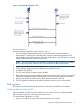
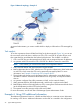
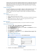
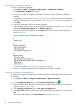
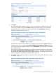

Figure 14 Network topology—Example 3
As network administrator, you want to enable IVMS to deploy its VPN tasks to CPEs managed by
BIMS.
Task analysis
To use the cooperation schema of BIMS and IVMS in the above network (Figure 14), you can set
the core switch as the hub device, and the two CPEs, CPE A and CPE B, as spoke devices, and
then create the IPsec tunnel between the hub and spoke devices. The workflow is as follows:
1. CPE A and CPE B access the Internet through ADSL and are assigned dynamic IP addresses.
2. An operator adds CPE records for CPE A and CPE B in BIMS to create two virtual CPEs.
NOTE: In this schema, you cannot use the BIMS zero-configuration solution.
3. CPE A and CPE B boot and send connection requests to BIMS.
4. BIMS authenticates the two CPEs. After the two CPEs pass the authentication, BIMS adds them
as real CPEs, which means the CPEs can be practically managed by BIMS. For more
information, see “Example 2: Deploying CPEs in branch offices.”
5. Through setting the device service parameters, IVMS is authorized to access BIMS device
information. It obtains information about BIMS devices using SOAP, and imports the BIMS
devices.
6. An operator configures IPsec VPN parameters in IVMS, such as network domain.
7. IVMS generates the IPsec VPN deployment task, and the task is synchronized to BIMS.
8. BIMS deploys the IPsec VPN configuration to CPEs, creating IPsec VPN between the hub device
(at the headquarters) and the CPEs (at the branches).
9. The operator views the execution results of the task in BIMS.
For more information, see HP IMC IPsec VPN Manager System Administrator Guide.
Example 4: Using CPE additional information
The additional information function is a flexible tool that helps you customize various information
for marking a CPE device. Additional information can be used as a variable in the configuration
26 Typical BIMS applications