HP Intelligent Management Center – Branch Intelligent Management System Administrator Guide Abstract This document describes how to administer the HP IMC Branch Intelligent Management System. HP Part Number: 5998-3834 Software Version: 5.
© Copyright 2013 Hewlett-Packard Development Company, L.P. Confidential computer software. Valid license from HP required for possession, use or copying. Consistent with FAR 12.211 and 12.212, Commercial Computer Software, Computer Software Documentation, and Technical Data for Commercial Items are licensed to the U.S. Government under vendor's standard commercial license. The information contained herein is subject to change without notice.
Contents 1 Introduction to BIMS....................................................................................8 BIMS capabilities......................................................................................................................8 Resource Management.........................................................................................................8 CPE Group.........................................................................................................................
3 Resource management..............................................................................34 Managing CPE devices...........................................................................................................34 Viewing all CPEs................................................................................................................34 Querying a CPE................................................................................................................34 Adding a CPE........
Adding a configuration template by importing a file..........................................................56 Modifying a configuration template......................................................................................57 Copying a configuration template........................................................................................57 Exporting a configuration template.......................................................................................58 Deploying CPE configurations..
Compliance Center...................................................................................85 Introduction............................................................................................................................85 Compliance workflow.............................................................................................................85 Managing check task..............................................................................................................
Recovering alarms from the All Alarms page........................................................................109 Deleting alarms from the All Alarms page...........................................................................109 Acknowledging all alarms.................................................................................................109 Editing maintenance experience........................................................................................
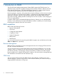
1 Introduction to BIMS The HP IMC Branch Intelligent Management System (BIMS) supports the TR-069 protocol, an application layer protocol for remotely managing end-user devices. TR-069 is based on the DSL Forum technical specification, CPE WAN Management Protocol, for communications between Customer-Premises Equipment (CPE) and Auto Configuration Servers (ACS). Network managers, engineers, and operators face complex challenges in their mission to manage various CPE devices in a centralized way.
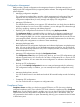
Configuration Management BIMS provides a central configuration and management function to facilitate managing and deploying the CPE configuration files (or segments) and the software. The configuration management portal integrates: • Managing configuration templates The configuration template library provides unified management of configuration files and segments.
System Configuration You can use the System Configuration function to configure: • System settings, including web management, polling and inform intervals, CPE access parameters, common password status, and ACS running log settings.
Figure 1 BIMS Overview page The expandable menu on the left is the Navigation Tree, which enables you to quickly browse to any other BIMS function. If you click the Overview icon on the top of the tree, the Overview page displays. When you first log in, no data is available on the default Overview page. After you add CPE devices to BIMS, the system generates statistics immediately, and displays them on the Overview.
Figure 2 BIMS workflow Workflow description: 1. Importing CPEs into BIMS: a. Plan your CPE authentication and deployment strategies and set BIMS system parameters according to these strategies. When a CPE sends a connection request to BIMS, BIMS checks whether the connection username and password in the request matches the related information configured in the authentication user or BIMS common password. Therefore, you must add authentication users or configure common password in advance. b.
3. Managing and maintaining BIMS, including: • Adding CPE classes • Configuring CPE group for CPE classification • Managing CPE interaction logs • Managing CPE configurations This includes managing, backing up, restoring, and comparing the configurations of deployed CPEs. • Performing compliance check This includes defining compliance policies and checking whether any CPE devices or CPE classes violate the corresponding compliance policy.
2 Typical BIMS applications The following scenarios are provided to help you better understand how BIMS is typically applied to aid in network management. Prerequisites of BIMS applications Before starting any BIMS procedures in the following scenarios, make sure you have: • Installed and configured the IMC base platform and BIMS service components. The IMC platform works as your network management system. • Established administrator access to the IMC base platform.
Task analysis To execute this scenario, you would: 1. Add virtual CPEs to BIMS. To add a CPE to BIMS, you must first add a CPE record to the CPE List, which contains the serial ID and OUI of the CPE. Any CPE listed in the CPE List which never practically accesses BIMS is called a virtual CPE. In this example, since the target CPEs belong to the same vendor—HP, you can use the quick adding function, which enables you to scan the CPE serial IDs with a barcode scanner. 2. 3.
2. Add virtual CPEs to BIMS. Add a CPE record containing CPE name, serial ID, OUI, and related information to the CPE List of BIMS. 3. 4. 5. 6. 7. 8. 9. Customize a startup configuration file, and create an automatic deployment task for the virtual CPEs. The target CPE boots and sends DHCP discover packet. The DHCP server replies with an Offer. The CPE sends a DHCP request to the DHCP server. The DHCP server replies with an ACK-Option 43, which contains the BIMS URL, connection username, and password.
5. Click OK. The CPE HP5820–V1 is added to BIMS as a virtual CPE. At the same time, BIMS clears the Serial ID and CPE Name fields, reserves other CPE values, and then automatically places the cursor over the Serial ID text box on the page. 6. To add the next virtual CPE, place your cursor over the Serial ID text box, use a barcode scanner to scan the serial ID of the second CPE, enter the CPE name as needed, and then click OK. NOTE: You can specify a name for each virtual CPE.
Figure 6 Adding a configuration template 4. Click OK. The configuration template hp5820_startup configuration.cfg appears in the startup configuration template folder. For more information, see “Creating a configuration template.” Creating an automatic deployment task To create an automatic deployment task: 1. Click Service > BIMS > Configuration Management > Deployment Guide. 2. 3. 4. 5. in the Auto Deploy Configuration On the Deployment Guide page, click the By CPE icon field.
Figure 7 Deploying a configuration template 6. 7. 8. 9. Click Next. If the configuration file hp5800_startup configuration.cfg contains variables, set values for the variables, and then click Next. BIMS sets the task name as Task+current time by default. You can specify a name for the automatic deployment task as needed. Enter a description for the task, and then click Finish. The automatic deployment task is created.
Figure 8 Network topology of CPE devices—Example 2 Task analysis To execute this scenario, you would: 1. Configure BIMS information on CPE devices. 2. Import the new software version to BIMS. 3. Create a software deployment task for upgrading the software on the MSR20–10 CPEs managed by BIMS. 4. Create an automatic software deployment task to deploy the new version of software to the newly-added MSR20–10 CPEs. The process of automatically deploying a CPE through BIMS is shown in Figure 9.
Figure 9 Automatically deploying a CPE Process description The following steps describe the process shown in Figure 9. 1. Plan and configure BIMS authentication users for each branch, and then inform the administrators in each branch of the BIMS URL, connection username and password. The administrators in the branches perform CPE initial configurations on the CPE devices, including setting the BIMS URL and connection information.
2. Configure the BIMS URL, connection username and password, as shown in Figure 10. Figure 10 Initial configuration command lines NOTE: The commands vary depending on the device type. For more information, see the user guide for the corresponding device. Importing CPE software to BIMS This task imports the latest version (V1.5) of CPE software saved in your local client to BIMS. To import the CPE software: 1. Click Service > BIMS > Configuration Management > Software Library. The Software List appears.
8. Enter a brief description of the software, and then click OK. Figure 11 shows an example of importing CPE software. Figure 11 Importing CPE software For more information, see ”Deploying CPE software.” Creating a software deployment task This task upgrades the software on the HP MSR20–10 CPEs currently managed by BIMS. To create an automatic software deployment task: 1. Click Service > BIMS > Configuration Management > Deployment Guide. 2. 3. 4. .
Figure 12 Deploying software 8. Click OK. You can view the execution result of the task on the Deployment Task page. For more information, see “Managing deployment tasks.” Creating an automatic software deployment task This task deploys the software V1.5 to the HP MSR20–10 CPEs that will be added into your network. To create an automatic software deployment task: 1. Click Service > BIMS > Configuration Management > Deployment Guide. 2. 3. 4. 5.
Figure 13 Automatically deploying software by CPE class 6. Click OK. For more information, see “Automatically deploying CPE software.” You can view the execution result of the task on the Deployment Task page. For more information, see ”Managing deployment tasks.” Example 3: BIMS working cooperatively with IVMS Similar to BIMS, IPsec VPN Manager System (IVMS) is an add-on service module of the HP IMC base platform which facilitates managing and monitoring IPsec VPN and DVPN.
Figure 14 Network topology—Example 3 As network administrator, you want to enable IVMS to deploy its VPN tasks to CPEs managed by BIMS. Task analysis To use the cooperation schema of BIMS and IVMS in the above network (Figure 14), you can set the core switch as the hub device, and the two CPEs, CPE A and CPE B, as spoke devices, and then create the IPsec tunnel between the hub and spoke devices. The workflow is as follows: 1.
template. That is, if the content of a configuration template contains a variable whose name is the same as the variable name of a CPE additional information entry, when deploying the configuration template BIMS automatically sets the value of the variable to the default value specified in the additional information. This is a typical application of CPE additional information, as described in the following example.
Customizing a configuration segment To create a configuration template: 1. Click Service > BIMS > Configuration Management > Configuration Templates. The Configuration Templates list appears. 2. Create a new folder or navigate to the folder to which you want to add the configuration template. For example, you can create a running configuration folder for storing the configuration template to be created. For more information, see “Creating a configuration template folder.” 3. 4. Click Add.
Figure 17 Deploying a configuration segment 6. Click Next. Since the configuration segment segment–1220.cfg contains a variable L, which is the same as the variable name of the Location additional information entry, in this case BIMS automatically sets the variable value as the default value of the Headquarter additional information entry as shown in Figure 18.
8. After you finish configuring the variables, set the deployment task attributes, and then click Finish. For more information, see “Deploying CPE configurations.” BIMS executes the task according to the task attributes, and deploys the segment to the target CPEs. Example 5: Using Compliance Center Compliance management helps solve potential configuration and security problems in your network.
7. 8. • Rule Type: Basic • Match Mode: Strict Match • Match Patterns: link-protocol PPP Click OK. Go back to the Add Compliance Policy page and test the added rule: a. b. Click the Test icon in the Test column of the link-protocol rule. On the Test Rule page, enter link-protocol PPP into the Test Content text box, and then click Test. A message saying “Test content matches rule link-protocol.” appears, which means the rule link-protocol passed the test. 9.
To fix the violating CPE: 1. On the Check Task page, select the check task link-protocol check, and then click the Fix icon 2. 3. 4. under the Fix column. On the Rule Violating Overview page, review the violating details form the list, and then select the check box to the left of the compliance policy link-protocol. Click Fix on the upper left corner of the page. As shown in Figure 20, enter link-protocol PPP in the Fixing Commands text box, and then click Next. Figure 20 Fixing Commands 5.
6. Click Finish. A results page appears, as shown in Figure 22. Figure 22 Results The prompt box on the top of the results page tells you whether the check task was created successfully. You can check task details, clone this task to add a new one, and add a deployment task directly. For more information, see ”Fixing a check task.
3 Resource management IMC provides a resource management function for recognizing CPE devices from the network and adding them into BIMS, including adding a CPE, adding CPEs in batches, and importing or exporting CPEs. BIMS enables you to provision a CPE or collection of CPEs based on basic information and additional information.
1. 2. Click Service > BIMS > Resource Management > All CPEs. On the All CPEs page, specify the following query conditions in the Query CPE pane: • CPE Name • CPE Class • Vendor • Serial ID • CPE Status • IP Address BIMS supports fuzzy query function, which enables you to specify an intact or partial query condition. For more information about the query condition, see “Viewing all CPEs.” 3. Click Query. The query results display in the CPE List. 4. Click Reset to reset the query conditions.
Additional information The customized additional information appears here only if you added it before. For more information about the additional information function, see “Adding CPE additional information.” 3. Click OK. The CPE that you added appears in the CPE List. Quickly adding CPEs To quickly add new CPE devices: 1. Click Service > BIMS > Resource Management > Add CPE. 2. On the Add CPE page, click Quickly Add CPE. 3. On the Quickly Add CPE page, specify the following: 4. 5.
Configuring a CPE CPE details offer a comprehensive management interface where most CPE configuration items are located. CPE details appear in the Basic Information and Additional Information panes. You can check the alarm status from the statistics chart in the CPE Details and the Recent 10 unrecovered alarms panes. You can also perform certain operations in the Action, Apply, and Configuration Management panes. Modifying CPE details To modify CPE device details: 1.
• Latest Running Configuration Backup—The file name of the latest running configuration backup file. Click the file name to open the Configuration File Details page, where you can check all details of the running configuration file. • Current Software—The current running software version. • Latest Available Software for Upgrade—The latest available software version that can be used for upgrade.
1. Click the WAN DSL Link icon . The WAN DSL Link Management page appears, as shown in Figure 23. Figure 23 WAN DSL Link Management 2. Select the query conditions, and then click Query. Then the query result appears in the WAN DSL link list. To view the WAN IP connection page: 1. Click the WAN IP Connection icon . The WAN IP Connection page appears, as shown in Figure 24. Figure 24 WAN IP Connection 2. Specify the query conditions in the Query WAN IP Connection pane, and then click Query.
2. Specify the query conditions in the Query WAN PPP Connection pane, and then click Query. The query results appear in the WAN PPP Connection List pane. To execute a remote reboot: • Click the Remote Reboot icon to reboot the CPE device from BIMS. To execute a factory reset: • Click the Factory Reset icon to reset the CPE configurations to the factory value. To change a CPE: • Click the Change CPE icon to replace the old CPE with a new one.
Modifying CPE additional information The CPE additional name information cannot be modified. To modify other CPE additional information parameters: 1. Click Service > BIMS > Resource Management > CPE Additional Information. 2. On the Add CPE Additional Information page, select the target CPE, and then click the Modify 3. 4. icon . On the Modify CPE Additional Information page, reset the parameter values. Click OK. Deleting CPE additional information To delete CPE additional information: 1.
5. Click OK to launch the importing process. The CPE Importing Results page appears, where you can check the import results. 6. Click Back to end the importing process. Configuring CPEs in batches You can use the Batch Operate function to configure CPE parameters in batches, which avoids accessing the CPE details page to do the configurations one by one. Configuring the inform interval This function enables you to set the interval at which the system polls the specified CPEs.
1. 2. 3. 4. 5. Click Service > BIMS > Resource Management > Batch Operate. On the Batch Operate page, click Configure File Transfer Type. On the Configure File Transfer Type page, click Select CPE. On the CPE List page, select the target CPEs, and then click OK. Specify the Transfer Type is HTTP or HTTPS, and then click Apply. Setting an auto restore strategy This function enables you to configure multiple CPEs in batches to automatically restore configuration or software to the baseline version.
2. On the Batch Operate page, click Data Model. The Data Model page appears, as shown as Figure 26. Figure 26 Data Model 3. 4. In the CPE List pane, click the Select CPE icon . On the CPE List page, specify the querying conditions, and then click Query, or click Query directly to query all CPEs. The available CPEs appear under the CPE List pane of the Data Model page. 5. 6.
• Click Service > BIMS > Resource Management > CPE Interaction Log. All interaction logs are displayed in the CPE Interaction Log list, which contains the following information. • CPE Name—The CPE name, which is set to “OUI + Serial ID” by default. You can customize this during the CPE adding procedure. You can click this link to open the specific CPE Details page. • OUI—The organizationally unique identifier number of the vendor. • Serial ID—The CPE serial ID number.
4 CPE group management A CPE group facilitates rights assignment to operators. You can create CPE groups, and add related CPEs to each CPE group for management. CPE groups are classified as follows: • Root group—Functions like a root directory. An administrator can assign the management right of a root group to other operators. • Subgroup—Functions like a subdirectory.
• ◦ Manage All Groups—Whether the operator has management access to all groups. ◦ Description—A description of the CPE group. CPE List lists all subgroups and CPEs within the selected CPE group. It contains: ◦ Status—The status of the associated subgroup or CPE as: – Normal—The CPE group is working normally. – Suspended—The CPE group has stopped working. – Unmanaged—The CPE group is currently not being managed. ◦ Subgroup/CPE Name—The name of a subgroup or CPE.
1. Do one of the following to open the Subgroup/CPE List page of a CPE group: • Click Service > BIMS > Overview, and then locate and click the link of a CPE group in the CPE Group Snapshot section to open the Subgroup/CPE List page of the CPE group. • Click Service > BIMS > CPE Group, and then select the Service tab, and then click the CPE List icon • 2. to open the Subgroup/CPE List page of the associated CPE group.
2. 3. Click the Delete icon Click OK. of a CPE subgroup entry. A dialog box appears for confirmation. Deleting CPEs from a CPE group To delete a CPE from a CPE group: 1. Navigate to the group or subgroup CPE List containing the CPE you want to delete. 2. Do one of the following: • Locate and click the Delete icon • Select one or more CPE entries in the CPE Group List, click Remove in the upper left corner of the list, and then click OK. of a CPE entry, and then click OK.
5 Configuration management BIMS provides central configuration and management functions to facilitate managing and deploying the CPE configuration files (or configuration segments) and CPE software.
In addition, BIMS provides a zero-configuration CPE deployment wizard, with which BIMS can automatically add a CPE and deploy an initial configuration to the CPE when it accesses BIMS for the first time. For more information, see “Typical BIMS applications.” Overview of the zero-configuration CPE deployment wizard You can directly configure and deploy CPEs from the IMC BIMS client without performing any operations on CPE devices. This is called a zero-configuration solution.
To open the zero-configuration CPE deployment wizard: 1. Click Service > BIMS > Configuration Management. The zero-configuration CPE deployment wizard opens. 2. View the flowchart, shown in Figure 27, and then click each operation icon to open the corresponding operation interface. Managing configuration templates BIMS uses a configuration template library to store and manage CPE configuration files or segments in hierarchy.
2. You can set query criteria by name, template type, and the stored folder to search for the configuration templates or folders you want to view. Specify the query conditions in the Query Condition pane, and then click Query. The configuration templates or folders matching your conditions are displayed in the Configuration Templates list. 3. 4. Click Reset to restore all configuration templates and folders stored at the template folder root level.
6. Click OK. The folder you created appears in the folder you selected. Modifying a configuration template folder You must have administrative level access to modify a configuration template or folder. To modify an existing configuration template folder: 1. Click Service > BIMS > Configuration Management > Configuration Templates. The configuration templates and folders stored at the template folder root level are displayed in the Configuration Templates list. 2.
1. Click Service > BIMS > Configuration Management > Configuration Templates. The configuration templates and folders stored at the template folder root level are displayed in the Configuration Templates list. 2. 3. Navigate to the folder where you want to add a configuration template. Click Add. The Add Configuration Template page appears. 4. Specify the following information: • Name—Specify a name for the configuration template.
address is used as the variable name. When you use this template to deploy a configuration file or segment, ${ip address} is replaced by the IP address you define. NOTE: The variable name cannot contain space characters and any of the following characters: ${}. ◦ To create a configuration segment in TR-069 Node Form format, click Select Node above the TR-069 Node form to open the Select Data Model dialog box.
7. 8. Enter a description for the configuration template you import. Click OK. The imported configuration template appears in the selected template folder. Modifying a configuration template You can modify any existing configuration templates except those stored in the Default Folder of the Configuration Template list. To modify a configuration template: 1. Click Service > BIMS > Configuration Management > Configuration Templates.
3. In the Configuration Templates list, click the Operation icon template you want to modify, and then click the Copy icon associated with the configuration from the popup operation list. The Copy Configuration Template page appears. 4. View the details of the configuration template and modify the related information as required. For more information, see “Creating a configuration template.” 5. Click OK to confirm your changes.
3. 4. Click the Delete icon associated to the configuration template you want to delete. Or, you can select the check boxes associated to the configuration templates you want to delete, and then click Delete. Click OK to delete the configuration template you select. Managing the software library BIMS uses the software library to store and manage all kinds of CPE software.
3. 4. On the Import CPE Software page, click the Source File to the right of the Source File field, and then click Browse.... In the Choose File to Upload dialog box, select the target software in your computer, and then click Open. The full path and name of the file you select appear in the Source File field. 5. Confirm the file you want to upload, and then click OK. The software file name appears in the Source File and Target File fields. 6.
3. Modify the following information as needed: • Applicable CPEs—Define the types of CPEs where the software you import can be deployed. You can click Select Class to add more CPE classes to the existing class list. Or, select one or more existing classes, and then click Delete Class to remove them from the Applicable CPEs list. NOTE: If you don’t configure this parameter, leaving the Applicable CPEs as null, you can select any CPEs when deploying the target software. • 4.
Deploying configurations and software using the Deployment Guide The Deployment Guide is a wizard that helps you deploy configuration files (segments) and software to the CPEs. BIMS provides the following two methods for deploying CPE configuration templates and software: • Manual deployment—Enables you to create a deployment task for the CPEs that are actually managed by BIMS. • Automatic deployment—Enables you to create an automatic deployment task for the specified virtual CPEs.
4. Configure the deployment strategies: • File Type to be Deployed—Select either startup configuration or running configuration. • Update Baseline Configuration—Select whether or not to update the baseline configuration of the CPEs to which you deploy configurations. The options include: • ◦ Update—After the CPE configuration is deployed on the target CPE, the CPE automatically backs up the new configuration file, and sets the new configuration as a baseline configuration.
8. Set the following attributes to specify how the task is executed: • Task Name—Enter a task name. By default, the task name is Task+current time. • Operation Type—Select One-off to create a task that is executed only once. Select Periodical to create a task that is executed periodically. A Periodical task can be executed monthly, weekly, or daily. • • 9. Operation Time—Set the task execution time. The options include: ◦ Immediately—Execute the deployment task immediately.
NOTE: If a CPE does not match the classes you specified in the Applicable CPEs list that is configured when you import the CPE software, you cannot add it to CPE-to-Deploy list. Otherwise, the corresponding Check Result prompts that it does Not match with software's CPE class, and you cannot proceed to the next step unless you remove such CPEs. For more information, see “Importing CPE software to BIMS.” 6. Click OK to create a deployment task.
of the new deployed template. In this scenario, the target CPE shuts down, and then starts up with the new startup configuration file. • Running configuration—If the configuration template is used to deploy a running configuration to the CPE, the target CPE applies the contents of the new deployed template to the existing running configuration file without restarting. NOTE: A configuration segment can only be deployed as the running configuration in a deployment task.
3. 4. 5. Select the configuration template to be deployed. Set the following task attributes: • Folder—Select the folder that contains the configuration template you want to deploy. • File Name—Select the configuration template that you want to deploy. Set the following attributes to specify how the task is executed: • Task Name—Enter a task name. By default, the task name is Task+current time. • Description—Enter the task description. Configure the deployment strategies.
Automatically deploying CPE software The Auto Deploy Software function enables you to create an automatic CPE software deployment task, which deploys the specified software to the CPE accessing BIMS for the first time. You can create a task by CPE or CPE class. • If you create an automatic deployment task by CPE, you can only select virtual CPEs. The virtual CPE must meet the following two conditions: ◦ The CPE record, including a CPE name, OUI, and serial ID, must be added or imported to the CPE list.
2. Click the By CPE Class icon in the Auto Deploy Software field. The Auto Deploy Software page appears. 3. 4. 5. 6. Click Select, and then select the software you want to deploy. Set the following attributes to specify how the task is executed: • Task Name—Enter a task name. By default, the task name is Task+current time. • Description—Enter the task description. Click Select Class, and select one or more classes of CPEs on the displayed dialog box.
In the Deployment Task management center, you can perform the following operations for all types of tasks: • View a deployment task list • View a deployment task details • View execution results of a deployment task • Modify a deployment task • Copy a deployment task • Execute a deployment task immediately • Suspend or resume a deployment task • Delete a deployment task NOTE: Only operators who have system administrator or network maintenance access can modify, copy, delete, immediately exec
3. • Task Type—The type of the deployment task. For more information, see “Managing deployment tasks.” • Creation Time—The date and time when the deployment task is created. • Creator—The user name of the operator who created the deployment task. • Start Time—The date and time when BIMS starts executing the deployment task. • End Time—The date and time when BIMS finishes executing the deployment task. • Modify—A Modify icon for modifying the corresponding deployment task.
Modifying a deployment task BIMS allows you to modify the related attributes of a deployment task. You cannot modify deployment tasks meeting any one of the following conditions: • The task status is Executing. • The type of task is Auto Restore Configuration to Baseline or Auto Restore Software to Baseline. To modify a deployment task: 1. Click Service > BIMS > Configuration Management > Deployment task. All deployment tasks are displayed in the Deployment Task List. 2. 3.
Suspending/resuming a deployment task If a deployment task is in the Waiting or Executing status, you can use this function to stop executing it. Also, you can resume suspended tasks. If you suspend a task in the Executing status, the started deployments in this task continue until the deployments are finished, while those yet to be started are not be executed. NOTE: If you suspend an auto CPE configuration deployment task or auto CPE software deployment task, the auto deployment task is disabled.
2. 3. The configuration details of the CPEs managed by BIMS are displayed in the CPE configuration list, which includes: • CPE Name—The name of the CPE managed by BIMS. Click the CPE name link to open the CPE Details page. For more information, see “Configuring a CPE.” • IP Address—The IP address of the CPE managed by BIMS. • CPE Class—The CPE class. For more information, see “Adding a CPE.” • Current Version—The current version of the software deployed on the associated CPE.
7. When creating the task successfully, the Result page provides the following functional links: • Task Details—Click to view the task details. For more information, see “Viewing deployment task details.” • Clone to Add—Click to create a new task by copying and modifying this task. For more information, see “Copying a deployment task.” • Add Deployment Task—Click to create a new task using the default parameters. For more information, see “Deploying CPE software.
After you manually back up the CPE configuration in the Configuration Center, the created auto backup plan task appears in the Backup Task List of the Backup Configuration page, from where you can view the task status and related information. For more information, see “Backing up CPE configurations.” Restoring a CPE configuration to baseline BIMS allows you to make a configuration file as baseline. With this function, you can restore the current CPE configuration to baseline as needed.
2. In the CPE configuration list, select the CPE you want to manage, click the corresponding 3. Operation icon to display an operation list, and then select Configuration Management. On the Configuration Management page of the specified CPE, view or set the following attributes: • CPE Name—The name of the current CPE. Click the name link to open the CPE Details page. • CPE Class—The class to which the current CPE belongs. For more information, see “Adding a CPE.
1. Click Service > BIMS > Configuration Management > Configuration Center. The Configuration Center page appears. 2. 3. In the CPE configuration list, click the Operation icon to display a operation list, and then select Configuration Management. On the Configuration Management page of the specified CPE, view the Configuration Backup History list on the Configuration Management page, which includes the following information: • Version—Whether the configuration fie is a baseline or common configuration.
1. In the Configuration Backup History list, click the Compare icon of the configuration files to be compared. associated with one The General Configuration Comparison page appears. 2. 3. 4. • In the Select Right File pane, click Select CPE, and then select the CPE whose configure file is to be compared with the target file. Select the type of file that you want to compare. Click OK, and then compare the two file in the displayed configuration file comparison dialog box.
3. On the Configuration Management page of the specified CPE, click the Software Deploy History tab to view the Configuration Backup History list, which includes the following information: • Update Result—The execution result of updating software on the current CPE. • Start Time—The date and time when the software deployment task started executing. • Finished Time—The date and time when the software deployment task finished.
1. Click Service > BIMS > Configuration Management > Backup Configuration. All backup tasks are displayed in the Backup Task List. 2. 3. View the following information in the Backup Task List: • Task Name—The name of the deployment task. Click the name link to view the task details. • Description—A brief introduction of the task. • Creation Time—The date and time when the deployment task is created.
4. Click Select CPE, select the CPEs for which you want to back up the configuration, and then click OK. The selected CPEs appear in the CPE List. NOTE: When you select CPEs for a backup task, BIMS automatically filters the CPEs configured with auto backup tasks. 5. Click OK. The task you create appears in the Backup Task List. Modifying a backup task To modify a backup task: 1. Click Service > BIMS > Configuration Management > Backup Configuration.
• Click Service > BIMS > Configuration Management > Backup History Record. All historical backup records are displayed in the Backup History List, where you can view the following information: • Task Name—The name of the backup task. Click the name link to view the task details. • Description—A brief introduction of the backup task. • Task Type—Whether the task is to back up the CPEs you specified or all CPEs that are managed by BIMS. • Execution Time—The date and time when the task is executed.
2. Select the CPE and configuration file to be compared at the left. The configuration files you can select include Current Startup Configuration, Current Running Configuration, Backup History, Baseline Configuration, and Configuration Templates. 3. 4. Select the CPE and configuration file to be compared at the right. Click OK. The comparison page appears, showing the differences between the selected files.
6 Compliance Center Introduction The BIMS compliance check function helps you check CPE devices based on every target CPE or CPE class. It uses a binding configured compliance policy and provides prompt feedback. Once it finds a CPE violating the compliance policy, Compliance Center shows you the violation details in multiple ways. In addition, you can fix the illegal configuration segment items, solving potential configuration and security problems in your network.
• Click Service > BIMS > Compliance Center > Check Task. All available check tasks are displayed in the Task List pane on the Check Task page. The Task List shows: • Status—The check task execution results. • Task Name—The task name. Click to open the specific Task Details page. • Execute Task—When you want to execute the check task. Available options are Immediately and Periodically. • Creation Time—When the check task was created.
• ◦ Severity Level—The severity level. ◦ Check Type—Whether the check target type is a CPE or configuration segment. Click a rule name to open the associated Rule Details page, as shown in Figure 28 Figure 28 Rule Details • Check the basic information and the configuration information of the rule. NOTE: c. d. e. 5. Click Close to close the widow. Click Back to go back to the Compliance Policy Details page.
g. 7. You can click the Delete icon them all. to delete a specific CPE, or click Delete All to delete When you finish the CPE and CPE class adding procedure, click OK to go back to the Check Task page. A message appears on the top of the Check Task page confirming that the check task adding procedure is successful. Modifying a check task To modify a check task: 1. Click Service > BIMS > Compliance Center > Check Task. 2. 3. 4. On the Check Task page, click the Modify icon in the target check task row.
Enabling or disabling a check task This function is available only when the check task execution is set to Periodically or the Operation column in the task list is empty. To enable or disable a check task: 1. Click Service > BIMS > Compliance Center > Check Task. 2. On the Check Task page, select a target check task, and click Enable or Disable under the Operation column to enable or disable the check task. Checking task execution results To check task execute results: 1.
Figure 29 Task Execution Results The Task Execution Results page provides the following information: Task Attributes 90 • Task Name—The task name. • Creator—Who created the check task. • Violating CPEs—The number of violated CPE. • Vulnerability Sum—The number of violated rules in the CPE. • Task Description—The check task description. • Violation Severity—The violation rate of each severity in a chart.
CPE Check Information CPE Check Information lists the CPE name, total vulnerabilities number, and the violating results for each severity level. To open the CPE Violating Results page, click the CPE name. For more information, see “Viewing CPE Violating Results.” Compliance Policy Check Information • Policy Name—Links to open the Compliance Policy Check Results page. For more information, see “Viewing compliance policy check results.” • Total CPEs—The total violated CPE numbers of each policy.
• Operation Type—Select the fixing operation type as One-off or Periodical. If you select One-off, it means the fixing operation can only be executed in this fixing round. If you select Periodical, it means the system can execute the fixing task periodically. • Operation Time If the Operation Type is One-off, select one of these options: ◦ Scheduled—Set an operation time by entering the value by following yyyy-mm-dd hh:mm:ss format, or click the Calendar icon and select a specific time.
Viewing the check task history list To view the check task history list: • Click Service > BIMS > Compliance Center > Task History. All historic tasks are displayed in the Task History List pane, including: • Task Name—Links to the Task Details page. • Description—The task description. • Start Time—When the task started. • End Time—When the task ended. • Execution Result—Links to the Execution Results page, and displays the execution result as Succeeded or Failed.
Figure 30 Compliance Policy Check Results 3. Check the following results details: Task Attributes • Task Name—The task name. • Creator—Who created the check task. • Violating CPEs—The number of violated CPE. • Vulnerability Sum—The number of violated rules in the CPE. • Task Description—The check task description. • Violation Severity—The violation rate of each severity in a chart. Compliance Policy Check Information • Compliance Policy Name—The compliance policy name.
Viewing CPE Violating Results To view the CPE violating results: 1. Click Service > BIMS > Compliance Center > Task History. 2. On the Task History page, click the icon under the Operation column of the target task.
3. Check the following results details: Task Attributes • Task Name—The task name. • Creator—Who created the check task. • Violating CPEs—The number of violated CPE. • Vulnerability Sum—The number of violated rules in the CPE. • Task Description—The check task description. • Violation Severity—The violation rate of each severity in a chart. CPE Check Information • CPE Name—The name of CPE and all belonging policies. • Description—The violation details for each policy.
Managing compliance policy Compliance policy is the core function of the Compliance Center and should be configured at the very beginning when you decide to start the compliance check procedure. BIMS allows you to add, modify, delete, and enable or disable a compliance policy. Furthermore, nine system-defined policies are provided based on typical scenarios which group the most common rules for use. You can select to use them directly or customize new policies according to your requirements.
3. 4. Select a severity level for the rule. When CPEs violate this rule, the system marks a severity level information accordingly. Select a check type as CPE, Interface, or Configuration Segment. If you select Interface or Configuration Segment, set identifiers as follows: 5. 6. 7. 8. 9. 98 • Start Identifier—Specifies where and which commands BIMS will check. For example, if you enter interface*, BIMS checks all command lines that begin with interface.
10. Select a rule type. The available options are Basic and Advanced. If the Rule Type is Basic, do the following: a. Specify the Match Mode value from the four available options: b. • Loose Match—Certain character strings are contained in the CPE configuration file. • Negative Loose Match—Any character strings of a rule are not included in the CPE configuration file. • Strict Match—All character strings and order of a rule match the CPE configuration file strictly.
1. 2. On the Add Compliance Policy page, click the Test icon . On the Rule Test page, enter the violations in the Test Content text box, and then click Test to display the testing results. For example, if you enter 123 in the Match Patterns box, and the Match Mode is Loose Match, then: • When you enter 123 in the Test Content, the test result is Test content matches rule. • When you enter 456 in the Test Content, the test result is Test content does not match rule.
7 System configuration Use the System Configuration functions to manage CPE classes, CPE authentication users, system settings, and the BIMS option tool. Managing CPE classes Use this function to manage the CPE classes in the system, including querying CPE classes, adding, modifying, and deleting CPE classes. Querying and viewing CPE class list information To query and view the CPE classes in the system: 1. Click Service > BIMS > System Configuration > CPE Class.
Managing CPE authentication users This function defines the username and password with which a CPE accesses BIMS. When a CPE sends a connection request to BIMS, BIMS first checks whether or not the username and password in the request match the corresponding information defined in the authentication user list. NOTE: Only an administrator can add and modify CPE authentication user information. Viewers and network maintenance technicians can only modify the user password.
Managing system settings Use this function to manage system settings, including web manager configuration, polling and inform intervals, CPE access parameters and adding policy, common password status, and ACS running log settings. To manage system settings: 1. Click Service > BIMS > System Configuration > System Settings. 2.
Otherwise, the CPE can't access BIMS. Use this setting to enable or disable a Common Password. • Do one of the following: ◦ Select the Common Password Status as Enabled, enter a Common Password, and then click OK. ◦ Select the Common Password Status as Disabled, and then click OK. ACS Running Log • Select the ACS Log Level as Fatal, Error, Warning, Info, or Debug, and then click OK.
8 CPE alarm management CPE alarm management enables you to manage the alarms reported from the managed CPEs and generated during the system operation. It contains four main functions: • Real-time Alarms—Enables you to view information on unrecovered alarms in real time, and to query, acknowledge and recover realtime alarms from the realtime alarms list. • All Alarms—Enables you to view alarms of all types including: recovered, unrecovered, acknowledged and unacknowledged.
NOTE: You can view alarms only for CPEs to which you have management access and control. Recovering realtime alarms Alarm recovery can be done by the system or by an operator. Operators can recover one or more alarms from the realtime alarms list. Recovering an alarm has the effect of clearing it from the Real-time Alarm view while retaining it in the alarm database for a period of time.
• Click Alarm > CPE Alarm > All Alarms. The All Alarms page appears, as shown in Figure 33. Figure 33 All Alarms page Viewing all alarms On the All Alarms page, you can view the following information: • Level—The current severity or alarm level status for the associated alarm. • Alarm Source—The CPE name, IP address, or both to which this alarm refers. Grayed-out CPE names or IP addresses indicate either that the alarm is generated by the IMC server or that the CPE is unmanaged.
Basic query To query for alarms using Basic Query: 1. On the All Alarms page, change to Basic Query mode by clicking the link on the upper right corner of the Alarm Query pane. 2. Select the query criteria: • Level—Query for a specific alarm or severity level. The default alarm level is All Levels. Select this option from the list. • CPE Name—Enter a CPE name or IP address in the text box to view alarms that refer to the specified CPE.
4. Click Reset to restore the default query criteria and display the alarms meeting the default query criteria. Recovering alarms from the All Alarms page You can recover alarms from the All Alarms page. When an alarm is recovered, the selected alarm instance is considered resolved and removed from notification functions, although recovered alarms can still be viewed from the All Alarms list. If an alarm is recovered by the system, the Recovery Status field shows .
NOTE: You can acknowledge alarms only for CPEs to which you have management access and control. To acknowledge one or more alarms from the All Alarms list: 1. Click Alarm > CPE Alarm > All Alarms. 2. On the All Alarms page, select the check boxes to the left of the alarm entries that you want to acknowledge. To acknowledge all the alarms at the same time, select the check box to the left of the Level tab. 3. Click Acknowledge on the upper left corner of the All Alarms list.
To view the Alarm Notification page: • Click Alarm > CPE > Alarm Notification. The Alarm Notification page appears, as shown in Figure 35. Figure 35 Alarm Notification page From this page, you can view the three main notification methods: • Mail Notification • Message Notification • Alarm Forwarding From this page, you can access the following information for each notification rule: • Rule Name—The names of existing notification rules.
To configure the mail server: 1. Click Alarm > CPE Alarm > Alarm Notification. 2. On the Alarm Notification page, click Configure Mail Server in the upper right corner of the page. 3. On the Configure Mail Server page, enter the Server Address. 4. Select whether to require a security connection (SSL). 5. Select whether to enable authentication. If yes, enter the Username and Password of the sender's mailbox. 6. Enter the sender’s email address. 7.
• Concerned Alarms—Do one of the following: ◦ Select All Alarms to forward all types of alarms. ◦ Select Selected Alarms to specify types of alarms for forwarding. Then click Select Alarm to the right of the new alarms list that appears, select the alarms on the resulting Select Alarm popup. You can remove unwanted alarms from the list by selecting the alarm, and then clicking Delete. Only the selected alarms are forwarded. • 5.
Configuring the SMSC server An SMSC server must be configured to enable the system to send alarm notifications using short messages. To configure the SMSC server: 1. Click Alarm > CPE Alarm > Alarm Notification. 2. On the Alarm Notification page, click Configure SMSC in the upper right corner of in the message notification pane. 3. On the SMSC Settings page, select the serial port connecting the message sending device to the SMSC server from the Connect Using list. 4. Select the Baud rate. 5.
• Concerned Alarms—Do one of the following: ◦ Select All Alarms to forward all types of alarms. ◦ Select Selected Alarms to specify types of alarms for forwarding. Then click Select Alarm to the right of the new alarms list that appears, select the alarms on the resulting Select Alarm popup. You can remove unwanted alarms from the list by selecting the alarm, and then clicking Delete. Only the selected alarms are forwarded. • 5.
1. 2. 3. Click Alarm > CPE Alarm > Alarm Notification. In the Alarm Forwarding pane on the Alarm Notification page, do one of the following: • To add a new rule, click Add to open the Add Alarm Forwarding page, and then proceed with step 3. • To modify a rule, click its Modify icon then proceed with step 4. to open the page for modifying the rule, and Enter a Rule Name for the notification rule. NOTE: This step is mandatory for adding an alarm forwarding rule.
Copying an alarm forwarding rule Use this function to quickly add a new alarm forwarding rule by copying an existing alarm forwarding rule. To copy an alarm forwarding rule: 1. Click Alarm > CPE Alarm > Alarm Notification. 2. 3. 4. 5. On the Alarm Notification page, click the Copy icon associated with the alarm forwarding rule you want to copy. On the Copy Alarm Forwarding page, rename the rule using a unique name. Make any necessary modifications to the rule. Click OK.
• Alarm Level—The current severity or alarm level status for the associated alarm definition. The value can be Critical, Major, Minor, Warning, and Info. • Alarm Filtering—The alarm filter status, Yes or No. When Yes is selected, BIMS ignores the alarms that match the alarm definition. When No is selected, BIMS records and processes the alarms that match the alarm definition. • Alarm Type—Whether the alarm type is Predefined or Vendor defined.
6. • Alarm Description—Enter a string to describe this alarm definition. This must match some or all of the content in the Syslog event description field for this definition to generate an alarm in BIMS. • Syslog Descriptor—Enter a Syslog descriptor to define this alarm. This is a key word to identify a Syslog message. • Syslog Description—Enter a Syslog description to define this alarm. This is the details of a Syslog message. • Alarm Cause—Enter the cause of an alarm.
9 BIMS reporting BIMS reporting provides statistical information on CPE assets and CPE connectivity performance. BIMS reports are generated from system-defined or user-defined templates. You can view the web-based reports or have the reports exported to Crystal Reports, Adobe Acrobat, Microsoft Excel, Microsoft Word, Rich Text, or Comma Separated Value formats. In addition, you can schedule reports to run regularly and have the results sent via email in different file formats.
1. Locate and click CPE Connectivity Count Report on the Report Template List pane. A Set Parameter page appears, as shown in Figure 37. Figure 37 Set Parameter page 2. Set the following parameters by selecting from the lists: • Parameter “Begin Time” and “End Time”—Specifies query time range. Options include: Custom Range, Last Hour, Last Day, Last Week, and Last Month. If you select Custom Range, you must specify: • 3. ◦ Begin Time—The query start time. ◦ End Time—The query end time.
2. On the Set Parameter page, set the parameters by selecting from the lists: • Parameter “Begin Time” and “End Time”—Specifies query time range. Options include: Custom Range, Last Hour, Last Day, Last Week, and Last Month. If you select Custom Range, you must specify: • 3. ◦ Begin Time—The query start time. ◦ End Time—The query end time. CPE Group—A CPE group or select All CPEs. Click OK.
The CPE Connectivity Summary Report displays the following information: • CPE Name—Indicates CPE names. • IP Address—Indicates the IP addresses of CPEs. • Availability (%)—Indicates the ratio of the time during which a CPE is connected to the ACS to the time span specified on the Set Parameter page. • Total Break Persistence (Minute)—Indicates the total time of all the breaks that occurred within the specified period of time.
1. Navigate to the Add Scheduled Report page in one of the following ways: • Click Report > Add Scheduled Report. • Click Report > All Scheduled Reports and then, click Add in the Scheduled Report List pane on the All Scheduled Reports page. The Add Scheduled Report page appears, as shown in Figure 38. Figure 38 Add Scheduled Report page 2. Select a BIMS template: a. Click Select. b. On the Query Template page, select BIMS Report from the Type list. c. Select a BIMS report template. d. Click OK. 3.
9. Set parameters for the selected report template in the Parameter Value box: NOTE: The parameters displayed in the Parameter Value box is related to the report template that you have selected. If the report template does not need setting any parameters, the Parameter Value box does not appear in this page. If you select the CPE Asset Report, skip this step. If you select the CPE Connectivity Count Report, CPE Connectivity Detail Report, or CPE Connectivity Summary Report, set the following parameters: a.
2. Click Report to view reports on the report main page. NOTE: The report main page is a blank page that can be customized to meet individual reporting needs. You must create the reports using the report templates before you can add them to the report main page. For more information, see HP IMC Base Platform Administrator Guide. Managing realtime BIMS reports You can configure your report main page to include any of the BIMS realtime reports for quick and easy access to the report.
10 Support and other resources Contacting HP For worldwide technical support information, see the HP support website: http://www.hp.
11 Documentation feedback HP is committed to providing documentation that meets your needs. To help us improve the documentation, send any errors, suggestions, or comments to Documentation Feedback (docsfeedback@hp.com). Include the document title and part number, version number, or the URL when submitting your feedback.
Glossary Ack status Acknowledged status of an alarm. This can be Acknowledged or Unacknowledged. ACS Auto-Configuration Server. The server that interacts with the CPE and uses the CWMP to manage the CPE. In BIMS, there is an ACS in each BIMS background. You can deploy multiple ACSs in a distributed way, each of which manages a certain number of CPEs, thus expanding the management capacity. ACS servers interact and synchronize data through the JGroup protocol.
direction. One peer requests the other peer to assign a specific tunnel and session ID through these control packets. Then, using this tunnel and session ID, data packets are exchanged with the compressed PPP frames as payload. L2TP Relay Layer Two Tunneling Protocol over Frame Relay. A mechanism to tunnel PPP sessions independent of the media it runs over, using virtual or switched circuits.
Index A access parameters configuring, 42 accessing the CPE Group page, 46 additional information adding, 40 deleting, 41 example, 26 modifying, 41 alarm definitions adding or modifying, 118 deleting, 119 managing, 117 querying, 118 viewing, 117 alarm forwarding managing, 115 alarm forwarding rules adding or modifying, 115 copying, 117 deleting, 117 enabling or disabling, 116 alarm notifications, 110 alarms unrecovered, 38 all alarms acknowledging, 109 editing maintenance experience, 110 managing, 106 query
restoring a backed up file, 77 viewing, 77 Configuration Center, 73 deploying CPE configurations, 75 deploying CPE software, 74 configuration comparison, 83 Configuration Management, 37 configuration management, 50 Deployment Guide, 62 deployment task, 69 configuration templates adding by importing a file, 56 copying, 57 creating, 54 creating a folder, 53 deleting, 58 deleting a folder, 54 exporting, 58 manually creating, 54 modifying, 57 modifying a folder, 54 organizing, 53 querying, 52 viewing, 52 config
I importing CPE files, 41 inform interval configuring, 42 installation, 10 Interaction Log viewing, 45 Interaction Log List, 44 introduction workflow introduction, 8 invalid characters, 53 IP ping test, 43 IVMS, 25 L logging on, 10 M mail notification rule adding or modifying, 112 copying, 113 deleting, 113 enabling or disabling, 113 mail notifications, 111 managing configuration backup history, 77 managing CPE configurations, 73 managing CPE software deploy history, 79 managing system settings, 103 manag