HP Integrated Lights-Out 2 User Guide for Firmware 2.
© Copyright 2005, 2010 Hewlett-Packard Development Company, L.P. The information contained herein is subject to change without notice. The only warranties for HP products and services are set forth in the express warranty statements accompanying such products and services. Nothing herein should be construed as constituting an additional warranty. HP shall not be liable for technical or editorial errors or omissions contained herein. Confidential computer software.
Contents Operational overview ................................................................................................................... 9 Guide overview ........................................................................................................................................ 9 New in this release of iLO 2 ....................................................................................................................... 9 iLO 2 overview ............................................
User accounts and access ............................................................................................................... 45 SSH key administration .................................................................................................................. 46 SSL certificate administration ........................................................................................................... 47 Two-factor authentication ...............................................................
iLO 2 BL c-Class tab ..................................................................................................................... 129 Enclosure bay IP addressing ......................................................................................................... 129 Dynamic power capping for server blades ...................................................................................... 131 iLO 2 Virtual Fan ..................................................................................
Configuring directories when schema-free integration is selected ....................................................... 180 Setting up management processors for directories ............................................................................ 181 HP Systems Insight Manager integration ...................................................................................... 183 Integrating iLO 2 with HP SIM ................................................................................................
No console replay while server is powered down ............................................................................ 202 Skipping information during boot and fault buffer playback .............................................................. 202 Out of Memory error starting Integrated Remote Console .................................................................. 202 Session leader does not receive connection request when IRC is in replay mode ..................................
Lights-Out Lights-Out Lights-Out Lights-Out Management Management Management Management classes ..................................................................................................... 218 attributes .................................................................................................. 218 class definitions ......................................................................................... 218 attribute definitions ............................................................
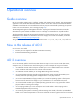
Operational overview Guide overview HP iLO 2 provides multiple ways to configure, update, and operate servers remotely. The HP Integrated Lights-Out 2 User Guide describes these features and how to use them with the browser-based interface and RBSU. Some features are licensed features and may only be accessed after purchasing an optional license. For more information, see "Licensing (on page 25).
proper server cooling. In addition to temperature monitoring, iLO 2 provides fan status monitoring and monitoring of the status of the power supplies, voltage regulators, and the internal hard drives. These examples are just a few ways iLO 2 is used to manage HP ProLiant servers from your office, home, or travel location. As you begin using iLO 2 and defining your specific infrastructure requirements refer to this guide for additional ways to simplify your remote server management needs.
HP Insight Essentials Rapid Deployment Pack integration HP Insight Essentials Rapid Deployment Pack integrates with iLO 2 to enable the management of remote servers and the performance of remote console operations regardless of the state of the operating system or hardware. The deployment server provides the ability to use the power management features of iLO 2 to power on, power off, or cycle power on the target server.
SMS should use the methods described in the specification for determining which IPMI features are enabled or disabled in the BMC (for example, using the Get Device ID command). If the server operating system is running and the health driver is enabled, any IPMI traffic through the KCS interface can affect the performance of the health driver and overall health performance of the system.
Assistance for all iLO 2 pages is available from iLO 2 Help. Links on each iLO 2 page provide summary information about the features of iLO 2 and helpful information to optimize its operation. To access pagespecific help, click the question mark (?) on the right side of the browser window. Typical user tasks are found under the System Status, Remote Console, Virtual Media, and Power Management tabs of the iLO 2 interface. These tasks are described in the "Using iLO 2 (on page 77)" section.
For graceful host operating system shutdown, HP SIM integration requires health drivers and Management Agents or remote console access. iLO 2 provides two interface drivers: • iLO 2 Advanced Server Management Controller Driver (health driver)—Provides system management support, including monitoring of server components, event logging, and support for the Management Agents. • iLO 2 Management Interface Driver—Enables system software and SNMP Insight Agents to communicate with iLO 2.
iLO 2 setup Quick setup To quickly setup iLO 2 using the default settings for iLO 2 Standard and iLO Advanced features, follow the steps below: 1. Prepare—Decide how you want to handle networking and security ("Preparing to setup iLO 2" on page 15) 2. Connect iLO 2 to the network ("Connecting to the network" on page 17). 3. If you are not using dynamic IP addressing, use the iLO 2 RBSU to configure a static IP address ("Configuring the IP address" on page 17). 4.
To access iLO 2 after connecting it to the network, the management processor must acquire an IP address and subnet mask using either a dynamic or static process: o Dynamic IP address is set by default. iLO 2 obtains the IP address and subnet mask from DNS/DHCP servers. This method is the simplest. o Static IP address is used to configure a static IP address if DNS/DHCP servers are not available on the network. A static IP address can be configured in iLO 2 using the RBSU.
Connecting to the network Typically iLO 2 is connected to the network in one of two ways. iLO 2 can be connected through a: • Corporate network where both ports are connected to the corporate network. In this configuration, the server has two network ports (one server NIC, and one iLO 2 NIC) connected to a corporate network. • Dedicated management network where the iLO 2 port is on a separate network. Configuring the IP address This step is necessary only if you are using a static IP address.
To configure a static IP address, use the iLO 2 RBSU with the following procedure to disable DNS and DHCP and configure the IP address and the subnet mask: 1. Restart or power up the server. 2. Press the F8 key when prompted during POST. The iLO 2 RBSU runs. 3. Select Network>DNS/DHCP, press the Enter key, and then select DHCP Enable. Press the spacebar to turn off DHCP. Be sure that DHCP Enable is set to Off, and save the changes. 4.
Setting up iLO 2 using iLO 2 RBSU HP recommends iLO 2 RBSU to initially set up iLO 2 and configure iLO 2 network parameters for environments that do not use DHCP and DNS or WINS. RBSU provides the basic tools to configure iLO 2 network settings and user accounts to get iLO 2 on the network. You can use RBSU to configure network parameters, directory settings, global settings, and user accounts. iLO 2 RBSU is not intended for continued administration.
2. Click Administration>Licensing to display the iLO 2 license activation screen. 3. Enter the license key. Press the Tab key or click inside a field to move between fields. The Activation Key field advances automatically as you enter data. Click Licensing to clear the fields and reload the page. 4. Click Install. The EULA confirmation appears. The EULA details are available on the HP website (http://www.hp.com/servers/lights-out) and with the license kit. 5. Click OK.
• CPQASM2.SYS, SYSMGMT.SYS, and SYSDOWN.SYS provide the iLO 2 Advanced Server Management Controller Driver support. PSP for Microsoft® Windows® products includes an installer that analyzes system requirements and installs all drivers. The PSP is available on the HP website (http://www.hp.com/support) or on the SmartStart CD. To install the drivers in the PSP: 1. Download the PSP from the HP website (http://www.hp.com/support). 2. Run the SETUP.
To install the drivers download the PSP from the HP website (http://www.hp.com/support) to a NetWare server. After downloading the PSP, follow the Novell NetWare component installation instructions to complete the installation. For additional information about the PSP installation, read the text file included in the PSP download. When using Novell NetWare 6.X, use the ATI ES1000 video driver that is provided by the operating system for best results.
Configuring iLO 2 iLO 2 configuration overview Typically, an advanced or administrative user who must manage users and configure global and network settings configures iLO 2. You can configure iLO 2 using the iLO 2 browser-based GUI or scripting tools such as CPQLOCFG and HPONCFG (described in the HP Integrated Lights-Out Management Processor Scripting and Command Line Resource Guide.
• Firmware Maintenance CD-ROM—Download the component to create a bootable CD that contains many firmware updates for ProLiant servers and options. • Scripting with CPQLOCFG—Download the CPQLOCFG component to get the network-based scripting utility, CPQLOCFG. CPQLOCFG enables you to use RIBCL scripts that perform firmware updates, iLO 2 configuration, and iLO 2 operations in bulk, securely over the network. Linux users should consider reviewing the HP Lights-Out XML PERL Scripting Samples for Linux.
If the firmware upgrade is interrupted or fails, attempt the upgrade again immediately. Do not reset the iLO 2 system before reattempting a firmware upgrade. Updating the firmware using the maintenance CD To use HP Smart Update Manager on the Firmware Maintenance CD: 1. Place the Firmware Maintenance CD on a USB key using the USB Key Creator Utility. 2. Copy CP009768.exe to /compaq/swpackages directory on the USB Key. 3. Follow HP Smart Update Manager steps to complete firmware update.
If you purchase the iLO Advanced Pack or the iLO Advanced Pack for BladeSystem with any Insight Control software suite or iLO Power Management Pack, HP provides Technical Support and Update Services. For more information, see "Support information (on page 221)." If you purchase the iLO Advanced Pack or the iLO Advanced Pack for Blade System as a one-time activation of licensed features, you must purchase future functional upgrades. For more information, see "Support information (on page 221).
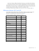
Feature iLO 2 Advanced iLO 2 Advanced for BladeSystem iLO 2 Standard iLO 2 Standard Blade Edition Power-related reporting* √ √ — — Dynamic power capping √ √ — — Group power capping √ √ — — Two-factor smart card authentication √ √ — — HP SIM single sign-on √ √ — — Kernel debugger for Windows √ √ — — Console replay √ √ — — Shared remote console √ √ — — Boot/fault console capture √ √ — — iLO video player (license required for capture) √ √ √ √ In addition t
To access local accounts, click Administration>User Administration>Local Accounts. iLO 2 Directory Accounts enables you to view iLO 2 groups and modify the settings for those groups. You must have the Administer Directory Groups privilege. To access Directory Accounts, click Administration>User Administration>Group Accounts. Adding a new user IMPORTANT: Only users with the Administer User Accounts privilege can manage other users on iLO 2. You can assign a different access privilege to each user.
3. Select User Administration>Local Accounts. 4. Click New. 5. Complete the fields. The following options are available: o User Name is displayed in the user list and on the home page. It is not necessarily the same as the Login name. The maximum length for a User Name is 39 characters. The User Name must use printable characters. o Login Name is the name that you must use when logging into iLO 2. The maximum length for a Login Name is 39 characters. The Login Name may only use printable characters.
Certificate button. Click this button to map a certificate to the user. After a certificate is mapped to the user account, a 40-digit thumbprint of the certificate appears, along with the Remove this Certificate button, which can be used to remove the certificate. If Two-Factor Authentication is enabled, a different certificate should be mapped to each user. A user who presents a certificate when connecting to iLO 2 is authenticated as the user to whom the certificate is mapped.
3. Click Delete User. A pop-up window is displayed asking, Are you sure you want to delete the selected user? Click OK. Group administration iLO 2 enables you to view iLO 2 groups and modify settings for those groups. You must have the Administer Directory Groups privilege. To view or modify a group: 1. Click Administration>User Administration>Group Accounts. 2. Select the group, and click View/Modify Group. The Modify Group page appears. Click Cancel to return to the Group Administration page.
Click Save Group Information to save updated information, or click Cancel to discard changes and return to the Group Administration page. Configuring iLO 2 access iLO 2 allows you to configure which services are enabled on iLO 2 and user access to iLO 2. To configure iLO 2 services options, click Administration>Access. The Services page (tab) appears. To configure iLO 2 access options (on page 40), click Administration>Access>Options (tab).
Parameter Default value Description Telnet Access Disabled This setting enables you to connect a telnet client to the Remote Console/Telnet port, providing access to the iLO 2 CLP. The following settings are valid: • Enabled—iLO 2 enables telnet clients to connect to the Remote Console/Telnet port. Network port scanners can detect that iLO 2 is listening on this port. Unencrypted communication is allowed between the iLO 2 CLP and telnet clients.
Parameter Default value Description Web Server SSL Port 443 This setting enables you to specify which port the embedded web server in iLO 2 uses for encrypted communications. Terminal Services Passthrough Disabled This setting enables you to control the ability to support a connection through iLO 2 between a Microsoft® Terminal Services client and Terminal Services server running on the host.
Parameter Default value Description Virtual Media Port 17988 This setting enables you to specify the port for virtual media support in iLO 2 communications. Shared Remote Console Port 9300 This setting enables you to specify the Shared Remote Console Port. The Shared Remote Console Port is opened on the client to allow additional users to connect to remote console in a peer-to-peer fashion. This port is only open when Shared Remote Console is in use.
Parameter Default value Description Raw Serial Data Port 3002 This setting specifies the Raw Serial Data port address.The Raw Serial Data port is only open while the WiLODbg.exe utility is being used to debug the host server remotely. Terminal Services Passthrough option Terminal Services is provided by the Microsoft® Windows® operating systems.
• Windows Server® 2008 On Windows Server® 2008 servers, the Terminal Services client and RDP connection is built-in. The client is part of the operating system and is activated using Remote Desktop sharing. To activate desktop sharing, select My Computer>Properties>Remote>Remote Desktop. The Terminal Services client in Windows Server® 2008 provides command line options and seamless launches from the Remote Console applet.
Errors that occur during installation and execution of the pass-through service are logged in the server Application Event Log. You can remove the pass-through service using Add or Remove Programs in the Control Panel. Enabling the Terminal Services Passthrough option By default, the Terminal Services Passthrough feature is disabled and can be enabled on the Administration>Access>Services page.
available environment. The seamless operation is available as long as the Terminal Services client is not started before Remote Console is available. If Remote Console is available and the Terminal Services client is available, Remote Console will start the Terminal Services client when appropriate.
If not, set the pass-through configuration to Enabled, and manually activate the terminal services client. Access options iLO 2 enables you to modify iLO 2 access, including connection idle time, iLO 2 functionality, iLO 2 RBSU, login requirements, CLI parameters, minimum password length, and server name. Settings on the Access Options page apply to all iLO 2 users. You must have the Configure iLO 2 Settings privilege to modify settings on this page.
Parameter Default value Descriptions Lights-Out Functionality Enabled This setting enables connection to iLO 2. If disabled, all connections to iLO 2 are prevented. The iLO 2 10/100 network and communications with operating system drivers are turned off if Lights-Out functionality is disabled. The iLO 2 Diagnostic Port for an HP ProLiant BL p Class server is also disabled.
Parameter Default value Descriptions Server Name — This setting enables you to specify the host server name. This value is assigned when using HP ProLiant Management Agents. If you do not use the agents and the host unnamed message appears, you can change it here. If the agents are running, the value you assign can be overwritten. To force the browser to refresh, save this setting, and press F5.
Security iLO 2 enables you to customize iLO 2 security settings. To access iLO 2 security settings, select Administration>Security.
o At least one numeric character o At least one special character o At least one lowercase character o At least one uppercase character Passwords issued for a temporary user ID, password reset, or a locked-out user ID should also conform to these standards. Each password must be a minimum length of zero characters and a maximum length of 39 characters. The default minimum length is set to eight characters.
Setting the iLO 2 Security Override Switch also enables you to flash the iLO 2 boot block. HP does not anticipate that you will need to update the iLO 2 boot block. If an iLO 2 boot block update is ever required, physical presence at the server will be required to reprogram the boot block and reset iLO 2. The boot block will be exposed until iLO 2 is reset. For maximum security, HP recommends that you disconnect the iLO 2 from the network until the reset is complete.
users, and the directory can enforce a stronger password policy. iLO 2 enables you to use local users, directory users, or both. Two configuration options are available: using a directory that has been extended with HP Schema ("Setting up HP schema directory integration" on page 142) or using the directory’s default schema (schema-free ("Setup for Schema-free directory integration" on page 138)).
SSL certificate administration iLO 2 enables you to create a certificate request, import a certificate, and view certificate administration information associated with a stored certificate. Certificate information is encoded in the certificate by the CA and is extracted by iLO 2. By default, iLO 2 creates a self-signed certificate for use in SSL connections. This certificate enables iLO 2 to work without any additional configuration steps.
Two-factor authentication Access to iLO 2 requires user authentication. This firmware release provides an enhanced authentication scheme for iLO 2 using two factors of authentication: a password or PIN, and a private key for a digital certificate. Using two-factor authentication requires that you verify your identity by providing both factors. You can store your digital certificates and private keys wherever you choose, for example, on a smart card, USB token, or hard drive.
Setting up two-factor authentication for the first time When setting up two-factor authentication for the first time, you can use either local user accounts or directory user accounts. For more information on two-factor authentication settings, see the "Two-Factor Authentication (on page 48)" section. Setting up local user accounts 1. Obtain the public certificate from the CA that issues user certificates or smart cards in your organization. 2.
After completing the authentication process, you have access to iLO 2. Setting up directory user accounts 1. Obtain the public certificate from the CA that issues user certificates or smart cards in your organization. 2. Export the certificate in Base64-encoded format to a file on your desktop (for example, CAcert.txt). 3. Open the file in Notepad, select all the text, and copy the contents to the clipboard by pressing the Ctrl+C keys. 4.
Two-factor authentication login When you connect to iLO 2 and two-factor authentication is required, the Client Authentication page prompts you to select the certificate you want to use. The Client Authentication page displays all of the certificates available to authenticate a client. Select your certificate. The certificate can be a certificate mapped to a local user in iLO 2, or a user specific certificate issued for authenticating to the domain.
the directory user's login name. Which client certificate attribute iLO 2 uses is determined by the Certificate Owner Field configuration setting on the Two-Factor Authentication Settings page. If Certificate Owner Field is set to SAN, iLO 2 obtains the directory user's login name from the UPN attribute of the SAN. If the Certificate Owner Field setting is set to Subject, iLO 2 obtains the directory user's distinguished name from the subject of the certificate.
Directory settings iLO 2 connects to Microsoft® Active Directory, Novell e-Directory, and other LDAP 3.0-compliant directory services for user authentication and authorization. You can configure iLO 2 to authenticate and authorize users using the HP schema directory integration or the schema-free directory integration. iLO 2 only connects to directory services using SSL-secured connections to the directory server LDAP port. The default secure LDAP port is 636.
• Use HP Extended Schema—Selects directory authentication and authorization using directory objects created with HP schema. Select this option if the directory has been extended with HP schema, and you plan to use it. • Use Directory Default Schema—Selects directory authentication and authorization using user accounts in the directory. Select this option if the directory is not extended with HP schema. User accounts and group memberships are used to authenticate and authorize users.
Instead of logging in as cn=user,ou=engineering,o=hp a search context of ou=engineering,o=hp allows login as user Example 2: If a system is Directory Directory Directory managed by Information Management, Services, and Training, search contexts like: User Context 1:ou=IM,o=hp User Context 2:ou=Services,o=hp User Context 3:ou=Training,o=hp Allow users in any of these organizations to log in using just their common names.
transmitted across the network. iLO 2 provides support for two of the strongest available cipher strengths; the Advanced Encryption Standard (AES) and the Triple Data Encryption Standard (3DES).
Connecting to the iLO 2 using AES/3DES encryption After enabling the Enforce AES/3DES Encryption setting, iLO 2 requires you to connect through secure channels (web browser, SSH, or XML port) using a cipher strength of at least AES or 3DES. To connect to iLO 2 through a browser, the browser must be configured with a cipher strength of at least AES or 3DES.
You can also access HP SIM SSO configuration settings using scripts, text files, and through a commandline using text-based clients such as SSH over the network or from the operating system on the host computer. Scripting SSO enables you to use the same SSO settings on all your LOM processors. For more information, example scripts, and CLP extensions to read, modify, and write HP SIM SSO configuration settings, see the HP Integrated Lights-Out Management Processor Scripting and Command Line Resource Guide.
http://:280/GetCertificate Cut and paste the certificate data from HP SIM into iLO 2. — Export the HP SIM server certificate from the HP SIM user interface by selecting Options>Security>Certificates>Server Certificate. Open the file using a text editor, and copy and paste all the certificate raw data into iLO 2. — Using command-line tools on the HP SIM server, the HP SIM certificate can be extracted using the tomcat-coded alias for the HP SIM certificate.
Users who log in to HP SIM are authorized based upon the role assignment at the HP SIM server. The role assignment is passed to the LOM processor when SSO is attempted. You can configure iLO 2 privileges for each role in the Single Sign-On Settings section. For more information about each privilege, see the section, "User administration (on page 27)." Using directory-based user accounts, SSO attempts to receive only the privileges assigned in this section. Lights-Out directory settings do not apply.
2. Click Administration>Security>Remote Console. The Computer Lock Settings page appears. 3. Modify the settings as required: o Windows—Use this option to configure iLO 2 to lock a managed server running a Windows® operating system. The server automatically displays the Computer Locked dialog box when a remote console session is terminated or the iLO 2 network link is lost.
F3 4. 0 d ~ Click Apply to save changes. This feature can also be configured using scripting or command lines. For more information, see the HP Integrated Lights-Out Management Processor Scripting and Command Line Resource Guide. Network The Network Settings and DCHP/DNS tabs of the Network section enable you to view and modify network settings for iLO 2. Only users with the Configure iLO 2 Settings privilege can change these settings.
• Subnet Mask is the subnet mask of the iLO 2 IP network. If DHCP is used, the Subnet Mask is automatically supplied. If not, enter the subnet mask for the network. • Gateway IP Address displays the IP address of the network gateway. If DHCP is in use, the Gateway IP Address is automatically supplied. If not, enter the network gateway address. • iLO 2 Subsystem Name is a name used by the iLO 2 subsystem.
iLO 2 Shared Network Port The iLO 2 Shared Network Port enables you to choose either the system NIC or dedicated iLO 2 Dedicated Management NIC for server management. When you enable the iLO 2 Shared Network Port, both regular network traffic, and network traffic intended for iLO 2 pass through the system NIC. iLO 2 provides support for servers that might not have an iLO 2 Dedicated Management NIC.
3. Select Network>NIC>TCP/IP, and press the Enter key. 4. In the Network Configuration menu, toggle the Network Interface Adapter Field to Shared Network Port by pressing the space bar. The Shared Network Port option is only available on supported servers. 5. Press the F10 key to save the configuration. 6. Select File>Exit, and press the Enter key. After iLO 2 resets, the Shared Network Port feature is active.
3. When prompted during POST, press the F8 key to enter iLO 2 RBSU. 4. Select Network>NIC>TCP/IP, and press the Enter key. 5. In the Network Configuration menu, toggle the Network Interface Adapter Field to ON by pressing the space bar. 6. Press the F10 key to save the configuration. 7. Select File>Exit, and press the Enter key. After iLO 2 resets, the iLO 2 Dedicated Management NIC port is active. To re-enable the iLO 2 Dedicated Management NIC using iLO 2 interface: 1.
You cannot set the iLO 2 IP address if DHCP is enabled. Disabling DHCP allows you to configure the IP address. The IP Address field also appears on the Network Settings page for your convenience. Changing the value on either page changes the DHCP setting. • IP Address is the iLO 2 IP address. If DHCP is used, the iLO 2 IP address is automatically supplied. If not, enter a static IP address. The IP Address field appears on the Network Settings page for your convenience.
Enabling SNMP alerts iLO 2 supports up to three IP addresses to receive SNMP alerts. Typically, the addresses used are the same as the IP address of the HP SIM server console. Only users with the Configure iLO 2 Settings privilege can change these settings. Users that do not have the Configure iLO 2 Settings privilege can only view the assigned settings.
3. After generating the alert, a confirmation screen appears. 4. Check the HP SIM console for receipt of the trap. SNMP generated trap definitions You can generate the following SNMP traps on BL c-Class servers and iLO 2: • ALERT_TEST is used to verify that the SNMP configuration, client SNMP console, and network are operating correctly. You can use the iLO 2 interface to generate this alert to verify receipt of the alert at the SNMP console.
Enter the IP address of the host server. The protocol (https://) and port number (:2381) are automatically added to the IP address or DNS name to allow access to the Insight Management Web Agents from iLO 2. If the Insight Manager Web Agent URL is set through another method (for example, CPQLOCFG), click the refresh button of your browser to display the updated URL. The Level of Data Returned setting controls the content of an anonymous discovery message received by iLO 2.
For example, after configuring Static IP Bay configuration for the blade in bay 1, subsequent blade additions to the enclosure assume subsequent addresses without DHCP. The network addresses are assigned by blade position bay 1: 192.168.1.1, bay 2: 192.168.1.2, and so on. Deploying subsequent blades does not demand extra configuration, and the network address corresponds to the bay number.
Configuring static IP bay settings Static IP bay settings are available on the BL p-Class tab and enable you to configure and deploy the blade server. When configuring these settings, you must use the blade in bay 1. The Enable Static IP Bay Configuration Settings checkbox, available on the Network Settings tab (not shown), allows you to enable or disable Static IP Bay Configuration. The new Enable Static IP Bay Configuration Settings option is only available on blade servers.
Primary WINS Server—Assigns a unique WINS server IP address on your network. Secondary WINS Server—Assigns a unique WINS server IP address on your network. Static Route #1, #2, and #3 (destination gateway)—Assigns the appropriate static route destination and gateway IP address on your network (the default IP values are 0.0.0.0 and 0.0.0.0, where the first IP address corresponds to the destination IP, and the second IP address corresponds to the gateway IP).
Click Cancel to close the automated setup wizard. Click Next to set up your blade server. The setup wizard will guide you through: 1. iLO 2 configuration 2. Server RAID verification 3. Virtual media connection 4. Software installation iLO 2 configuration screen This screen enables you to change the following settings: • Administrator password. HP recommends changing the default password. • Network configuration settings.
• Click Default Settings to automatically configure the RAID level based on the number of installed drives. You are prompted to verify that you want to reset the RAID level because this could result in loss of data. Resetting the RAID level requires a server power-on or reboot. iLO 2 displays a page indicating that this action is occurring. The page is refreshed automatically every 10 seconds. After the server reboots, the next page in the installation wizard displays again.
If Enable NIC is set to Yes, the diagnostic port is enabled. • Transceiver Speed Autoselect • Speed • Duplex • IP Address Use this parameter to assign a static IP address to iLO 2 on your network. By default, the IP address is assigned by DHCP. By default, the IP address is 192.168.1.1 for all iLO 2 Diagnostic Ports. • Subnet Mask o Use the subnet mask parameter to assign the subnet mask for the iLO 2 Diagnostic Port. By default, the subnet mask is 255.255.255.0 for all iLO 2 Diagnostic Ports.
Using iLO 2 System status and status summary information When you first access iLO 2, the interface displays the Status Summary page with system status and status summary information, and provides access to health information, system logs, and Insight Agent information. The options available in the System Status section are: Summary, System Information, iLO 2 Log, IML, Diagnostics, iLO 2 User Tips, and Insight Agents.
• TPM Status—Displays TPM status configuration. If the host system or System ROM does not support TPM, TPM Status does not appear in Status Summary page. For more information, see "Trusted Platform Module support." • Server Power—Displays the current power state of the server (ON/STANDBY) when the page was loaded and is a link to Server>Power Management. Users with virtual power and reset privilege can also use the Momentary Press button.
System Information Summary System Information displays the health of the monitored system. Many of the features necessary to operate and manage the components of the HP ProLiant server have migrated from the health driver to the iLO 2 microprocessor. These features are available without installing and loading the health driver for the installed operating system. The iLO 2 microprocessor monitors these devices when the server is powered on during server boot, operating system initialization, and operation.
Monitoring the fan sub-system includes the sufficient, redundant, and non-redundant configurations of the fans. Fan failure is a rare occurrence, but to ensure reliability and uptime, ProLiant servers have redundant fan configurations. In ProLiant servers that support redundant configurations, fan or fans might fail and still provide sufficient cooling to continue operation.
Processors The Processors tab displays the available processor slots, the type of processor installed in the slot, and a brief status summary of the processor subsystem. If available, installed processor speed in MHz and cache capabilities are displayed. Memory The Memory tab displays the available memory slots and the type of memory, if any, installed in the slot. NIC The NIC tab displays the MAC addresses of the integrated NICs. This page does not display add-in network adapters.
view the event log even when the server is off can be helpful when troubleshooting remote host server problems. You can sort the log by clicking the header of any column of data. After the sort completes, clicking the same column header again sorts the log in reverse of its current order. Very large logs will take several minutes to sort and display. You can clear the events in this log on the server's Insight Manager Web Agents home page.
o Use the Debug feature if a software application hangs the system. The Generate NMI to System button can be used to engage the operating system debugger. o Initiate the dump of an unresponsive host if you want to capture the server context. The Virtual Power and Reset privilege is required to generate an NMI. An unexpected NMI typically signals a fatal condition on the host platform.
iLO 2 Remote Console iLO 2 Remote Console redirects the host server console to the network client browser, providing full text (standard), graphical mode video, keyboard, and mouse access to the remote host server (if licensed). iLO 2 uses virtual KVM technology to improve remote console performance comparable with other KVM solutions.
Remote console access to the host server after server POST is a licensed feature available with the purchase of optional licenses. For more information, see "Licensing (on page 25)". To access iLO 2 Remote Console, click Remote Console. The Remote Console Information page appears. Remote Console overview and licensing options Remote Console and Integrated Remote Console connections are graphical and must be rendered using a client program that can process iLO 2 graphics commands.
• High Performance Mouse settings can help alleviate remote console mouse synchronization issues, but this feature is not supported on all operating systems. The effects of changing the settings take place when remote console is started or restarted. The following options are available: o Disabled—Enables the mouse to use the relative coordinates mode which is compatible with most host operating systems.
o Export enables you to trigger an export manually. o Export username is the username for the web server that is specified in the URL. o Password is the password of the web server that is specified in the URL. After making changes, click Apply. • Serial Port Configuration displays the current settings of the system serial ports and the Virtual Serial Port. The Settings for the system and virtual serial ports are also displayed, showing the COM ports in use and IRQ numbers.
information, refer to "Remote Console hot keys (on page 87)." The following table lists keys available to combine in a Remote Console hot key sequence. ESC F12 : o L_ALT "" (Space) < p R_ALT ! > q L_SHIFT # = r R_SHIFT $ ? s INS % @ t DEL & [ u HOME ~ ] v END ( \ w PG UP ) ^ x PG DN * _ y ENTER + a z TAB - b { BREAK .
Hot keys and international keyboards To set up hot keys on an international keyboard, select keys on your keyboard in the same position on a US keyboard. To create a hot key using the international AltGR key, use R_ALT in the key list. Use the US keyboard layout shown to select your keys. Shaded keys do not exist on a US keyboard. • The green shaded key is known as the Non-US \ and | keys on an international keyboard.
feature available with the purchase of optional licenses. For more information, see "Licensing (on page 25)". The Integrated Remote Console supports four simultaneous remote console sessions with the same server if enabled through the Remote Console Settings screen, SMASH CLI (OEM), or RIBCL. For more information about using multiple remote console sessions, see the section, "Shared Remote Console (on page 94).
o • Replay file—Displays an Open dialog box enabling you to view a previously saved file. After you select a file and click Open, the Remote Console menu changes to the Replay Console menu. Replay (play icon on the main menu)—Displays the Replay Console. The Replay Console provides playback control of the selected data buffer and displays elapsed playback time. The Replay Console has the following options: o Click Play to start the playback.
• Drive—Displays all available media. • Power (green power icon)—Displays the power status and allows you to access the power options. The power button is green when the server is powered up. When you press Power the Virtual Power Button screen appears with four options: Momentary Press, Press and Hold, Cold Boot, and Reset System. When either the Drives or Power button is pressed, the menu displayed remains open even when the mouse is moved away from the menu bar.
location similar to a USB tablet mouse. A conventional mouse sends relative position information (such as the mouse has moved 12 pixels to the right). The host computer can modify relative position information to enable features like mouse acceleration. When using the Remote Console, the client is not aware of these modifications. Therefore, synchronization between the client and host mouse cursors fails.
Shared Remote Console Shared Remote Console is an iLO 2 feature that allows the connection of up to four sessions on the same on the same server. This feature does not replace the Acquire feature described in "Acquiring the Remote console (on page 97)" or allow full-access clients (read/write) to control power. Shared Remote Console does not support passing server host designation to another user or a failed user connection to reconnect after failure.
Using HP iLO Video Player HP iLO Video Player enables you to playback iLO 2 console capture files without installing iLO 2 on your local system. iLO Video Player is designed as a typical media player with similar controls. You can run iLO Video Player as a standalone application on either a server or client. Typically, the application is located on the client. iLO 2 capture files are created using iLO 2 Console Capture feature, see "Using Console Capture (on page 94).
• Help o Help Topics—Opens the iLO Video Player help file. o About—Opens the iLO Video Player About page. iLO Video Player controls Control Name Function Play/Pause Starts playback if the currently selected file is not playing or is paused. If playback is in progress, it pauses the file. If no file is selected, the button is disabled. Stop Stops playback. If no file is selected, the button is disabled. Skip to Start Restarts playback from the beginning of the file.
Acquiring the Remote Console When the Remote Console Acquire setting on the Remote Console Settings screen is enabled, the Remote Console page displays the Acquire button. If you have opened the Remote Console page and are notified that another user is currently using Remote Console, clicking the Acquire button ends the other user's Remote Console session and starts a Remote Console session in your current window.
client operating systems (on page 13)" section. Remote Console is a licensed feature available with the purchase of optional licenses. For more information, see "Licensing (on page 25)". Remote Console uses dual cursors to help you distinguish between the local and remote mouse pointers. The client computer's mouse cursor appears in the Remote Console as a crosshair symbol.
• Close ends the Remote Console session and closes the Remote Console window. Recommended client settings Ideally, the remote server operating system display resolution should be the same resolution, or smaller, than that of the browser computer. Higher server resolutions transmit more information, slowing the overall performance. Use the following client and browser settings to optimize performance: • • • Display Properties o Select an option greater than 256 colors.
The Remote Console uses Virtual KVM and does not provide a true text-based console. iLO 2 uses the video adapter DVO port to access video memory directly. This method significantly increases iLO 2 performance. However, the digital video stream does not contain useful text data. Data obtained from the DVO port represents graphical data (non-character-based), and is not comprehensible ASCII or text data. This video data cannot be rendered by a text-based client application such as telnet or SSH.
o Other text-based operating systems Text mode screen support does not include graphics, other VGA text resolutions (132x48, 80x48), or other text resolutions implemented through a driver (implemented graphically).
When using iLO 2 Text Console, iLO 2 can emulate character mapping between the client, telnet, and the server. The default mapping is the USB 101-keyboard translation (or no translation). To control the translation, use the xlt option with the appropriate reference number.
Character value Description Mapped equivalent 0x1E Up pointer ^ 0x1F Down pointer v 0xFF Shaded block blank space Using a Linux session You can run an iLO 2 virtual serial port on a Linux system, if the system is configured to present a terminal session on the serial port. This feature enables you to use a remote logging service. You can remotely log on to the serial port and redirect output to a log file. Any system messages directed to the serial port are logged remotely.
Using the iLO 2 remote serial console, the remote user is able to perform operations such as interacting with the server POST sequence and operating system boot sequence; establishing a login session with the operating system, interacting with the operating system; and executing and interacting with applications on the server operating system. Users of the Microsoft® Windows Server™ 2003 operating system have the ability to execute the EMS subsystem through the remote serial console.
server serial port, intercepts and retransmits outgoing data to the Remote Serial Console client, receives incoming data (from the Remote Serial Console client), and retransmits it to the system ROM. After the server completes POST, the server system ROM transfers control to the operating system boot loader. If you are using Linux, you can configure the operating system boot loader to interact with the server serial port instead of the keyboard, mouse, and VGA console.
during the system POST sequence, and you can view and modify the POST. After disconnecting the Remote Serial Console session, the iLO 2 firmware resets the dynamic flag to inform the server system ROM that the session is no longer active. Then, the server system ROM cancels the redirection to the server serial port. The system ROM RBSU setup must be configured to use iLO 2 Virtual Serial Port for this enhancement to be operational.
[operating systems] multi(0)disk(0)rdisk(0)partition(1)\WINDOWS="Windows Debug (com2)" /fastdetect /debug /debugport=com2 /baudrate=115200 If the server is configured to boot into debug mode, and a normal virtual serial port connection is established while the server is booting, several bytes of debug data are sent to the virtual serial port client. To avoid this, do not boot the server into debug mode while a normal virtual serial port connection is in use.
• -t = —Uses a telnet connection indirectly through this utility from the debugger. Socket connection to socket 3002 is the default setting. • -u Username = —Sets the Username for iLO 2 login. If not provided username is requested. is a series of characters. Options can occur in any order. Example command lines: • To connect to iLO 2 at 16.100.226.57, validate the user with the user name of admin with the password mypass, and start WinDBG.
To access iLO 2 Virtual Media devices using the browser-based interface, click Virtual Media>Virtual Media Applet. An applet loads in support of the Virtual Floppy or Virtual CD/DVD-ROM device. You can also access virtual media through the Integrated Remote Console. The Integrated Remote Console enables you to access the system KVM and control Virtual Power and Virtual Media from a single console under Microsoft® Internet Explorer.
2. Select the drive letter of the desired local floppy or USB key drive on your client PC from the dropdown menu. To ensure the source diskette or image file is not modified during use, select the Force read-only access option. 3. Click Connect. The connected drive icon and LED will change state to reflect the current status of the Virtual Floppy Drive. To use an image file: 1. Select Local Image File within the Virtual Floppy/USBKey section of the Virtual Media applet. 2.
Virtual Floppy/USB Key operating systems notes • MS-DOS During boot and MS-DOS sessions, the Virtual Floppy device appears as a standard BIOS floppy drive. This device appears as drive A. If a physically attached floppy drive exists, is obscured and unavailable during this time. You cannot use a physical local floppy drive and the Virtual Floppy simultaneously.
3. Insert the media into the local floppy drive, select a diskette drive, and click Connect. Alternatively, select a diskette image to be used and click Connect. In NetWare 6.5, use the lfvmount command on the server console to assign the device a drive letter. The NetWare 6.5 operating system will pick the first available drive letter for the Virtual Floppy drive. The volumes command can now be used by the server console to show the mount status of this new drive.
This modification enables the mtools suite to access the Virtual Floppy as v. For example: mcopy /tmp/XXX.dat v: mdir v: mcopy v:foo.dat /tmp/XXX Changing diskettes When using the iLO 2 Virtual Floppy or USB key drive, and the physical diskette drive on the client machine is a USB diskette drive, disk change operations will not be recognized.
3. Click Connect. To use an image file: 1. Select Local Image File within the Virtual CD/DVD-ROM section of the Virtual Media applet. 2. Enter the path or file name of the image in the text box or click Browse to locate the image file using the Choose Disk Image File dialog. 3. Click Connect. The connected drive icon and LED will change state to reflect the current status of the Virtual CD/DVDROM.
• Linux o Red Hat Linux On servers with a locally attached IDE CD/DVD-ROM, the virtual CD/DVD-ROM device is accessible at /dev/cdrom1. However, on servers without a locally attached CD/DVD-ROM, such as the BL-class blade systems, the virtual CD/DVD-ROM is the first CD/DVD-ROM accessible at /dev/cdrom.
4. Click Create. The virtual media applet begins the process of creating the image file. The process is complete when the progress bar reaches 100%. To cancel the creation of an image file, click Cancel. The Disk>>Image option is used to create image files from physical diskettes or CD-ROMs. The Image>>Disk option is not valid for a Virtual CD-ROM image. The Disk>>Image button changes to Image>>Disk when clicked.
• Red Hat and SLES Linux Linux supports the use of Virtual Folder. Virtual Folder uses a FAT 16 file system format. For more information, see the section, "Mounting USB Virtual Media/USBKey in Linux (on page 112)." Power management iLO 2 Power Management enables you to view and control the power state of the server, monitor power usage, monitor the processor, and modify power settings. The Power Management page has four menu options: Server Power, Power Meter, Processor States, and Settings.
• Automatically Power On Server enables iLO 2 to turn on a server when power is applied, such as when the server is plugged in, or when a UPS is activated after a power outage. You must have Virtual Power and Reset privilege to alter this setting. If power is unexpectedly lost while the server is powering up, the server always powers back on, even if Automatically Power On Server is set to No. • Power On Delay is used to stagger server power-on in a data center.
o HP Static High Performance Mode sets the processor to the highest supported processor state and forces it to stay in that state. o Enable OS Control Mode sets the processor to maximum power. After selecting a Power Regulator for ProLiant option, click Apply to save the setting. The server requires a reboot for the change to take affect. These settings cannot be changed while the server is in POST.
o Warnings Triggered By—Determines if warnings are based on peak power consumption, average power consumption, or disabled. o Warning Threshold—Sets the threshold at which power consumption must remain above in order to trigger an SNMP alert. o Duration—Sets the length of time, in minutes, that power consumption must remain above the warning threshold before an SNMP alert is triggered. The maximum duration allowed is 240 minutes and must be a multiple of 5. To use your selected settings, click Apply.
• Present Power Cap displays the current power cap setting. The 24-Hour History section displays the following: • Average Power Reading displays the average of the power readings from the server over the last 24hour period. If the server has not been running for 24 hours, the value is the average of all the readings since the server was booted. • Maximum Power displays the maximum power reading from the server over the last 24-hour period.
differently for each p-state the processor was in, with each colored portion scaled to represent the percentage of the total time the processor spent in that p-state. Pausing the mouse over the bar graph displays a tool tip that indicates the numeric percentage that portion of the bar represents. Power efficiency iLO 2 enables you to implement improved power usage using a High Efficiency Mode (HEM). HEM improves the power efficiency of the system by placing the secondary power supplies into step-down mode.
Graceful shutdown The ability of the iLO 2 microprocessor to perform a graceful shutdown requires cooperation from the operating system. In order to perform a graceful shutdown, the health driver must be loaded. iLO 2 communicates with the health driver, and the appropriate operating system method of safely shutting the system down to ensure data integrity is performed.
The server blade must be properly cabled for iLO 2 connectivity. Connect to the server blade with one of the following methods: • Through an existing network (in the rack)—This method requires you to install the server blade in its enclosure and assign it an IP address manually or using DHCP. • Through the server blade I/O port o In the rack—This method requires you to connect the local I/O cable to the I/O port and a client PC.
• Rack name • Logged-in iLO Location This section annotates the blade you are logged into. You can only configure blade settings for this blade. • Selected Bay Location This section annotates the currently selected bay. You can view information for many different types of components, including blades, power supplies, network components, and enclosures. • Enclosure Details Information about a particular enclosure is viewed by selecting Details located on the enumerated enclosure headers.
• Power On Control o Power Source o Enable Automatic Power On o Enable Rack Alert Logging (IML) Enclosure information Enclosure information is specific to the selected enclosure. Information about a particular enclosure is viewed by selecting Details located on the enumerated enclosure headers. A limited amount of rack information is available, including the name and serial number A basic set of information is available for the enclosures that do not contain the blade that you are logged into.
Power enclosure information The Power Enclosure Information page provides diagnostic information regarding the power management module and the power components contained in the power enclosure. This information provides an overview on the health and condition of the power enclosure and components.
iLO 2 control of ProLiant BL p-Class server LEDs iLO 2 can monitor BL p-Class servers through POST tracking and the Server Health LED. Server POST tracking Feedback is limited while the server is booting because of the headless nature of the ProLiant BL p-Class servers. iLO 2 provides boot-time feedback by flashing the Server Health LED green during server POST. The LED is set to solid amber if the boot is unsuccessful. The LED is set to solid green at the end of a successful boot.
You can access iLO 2 through the HP Onboard Administrator iLO option (on page 132) using the Web Administration (on page 133) link or directly. To log in to iLO 2 directly, see the "Log into iLO 2 for the first time ("Logging in to iLO 2 for the first time" on page 18)" section for more information. iLO 2 BL c-Class tab The BL c-Class tab of the iLO 2 web interface enables you to access the Onboard Administrator and the BladeSystem Configuration Wizard.
o Manual—If your facility prefers static IP address assignment, you can individually change each of the server blade iLO 2 ports and interconnect module management ports to unique static addresses or use EBIPA to assign a range of static IP addresses to individual server blade and interconnect module bays.
Field Possible value Description Beginning Address ###.###.###.### where ### ranges from 0 to 255 Beginning IP address for the device or interconnect bays. Click the arrow next to the Beginning Address field, and click Update List to update the Device List or Interconnect List. Subnet Mask ###.###.###.### where ### ranges from 0 to 255 Subnet mask for the device or interconnect bays Gateway ###.###.###.
An optional setting that enables you to set a cap on a group of servers in an enclosure. Set the cap between the values shown above the Enclosure Dynamic Power Cap field. These values are based on the enclosure's current configuration. As the servers run, the demand for power varies for each server. A power cap for each server is set to provide the server with enough power to meet its workload demands while still conforming to the Enclosure Dynamic Power Cap.
Clicking the links in this section will open the requested iLO 2 sessions in new windows using SSO, which does not require an iLO 2 username or password to be entered. If your browser settings prevent new windows from opening, the links will not function properly. For help with turning off pop-up window blockers, see online help. Web Administration The Web Administration link on the HP Onboard Administrator interface accesses the iLO 2 GUI.
Feature BL c-Class BL p-Class Enclosure communications Ethernet i2c Enclosure-based IP addressing DHCP SBIPC Enclosure authentication to iLO 2 Mutual Not supported Server fan Virtual Physical Blade server information and configuration Unrestricted Restricted Power-on override Not supported Supported Front dongle SUV (no iLO 2) SUVi Rack management Full support through HP Onboard Administrator Limited support through iLO 2 Using iLO 2 134
Directory services Overview of directory integration iLO 2 can be configured to use a directory to authenticate and authorize its users. Before configuring iLO 2 for directories, you must decide whether or not you want to use the HP Extended schema option. The advantages of using the HP Extended schema option are: • There is much more flexibility in controlling access. For example, access can be limited to a time of day or from a certain range of IP addresses.
• Standards—Lights-Out directory support builds on top of the LDAP 2.0 standard for secure directory access. Advantages and disadvantages of schema-free directories and HP schema directory Directories enhance security, enabling you to manage access and rights from a centralized location. Directories also enable flexible configuration. Some directory configuration practices work better with iLO 2 than others.
Advantages of using schema-free directory integration: o There is no need to extend the directory schema. o When ActiveX controls are enabled in the browser and login, NetBIOS and e-mail formats are supported. o Little or no setup is required for users in the directory. If there is no setup, the directory uses existing users and group memberships to access iLO 2.
For information about how to extend the schema and configuration of directory settings information, see Integrating HP ProLiant Lights-Out processors with Microsoft® Active Directory (http://h20000.www2.hp.com/bc/docs/support/SupportManual/c00190541/c00190541.pdf). • Certificate requirements iLO 2 must communicate with the directory using LDAP over SSL. This communication requires the directory server to have a certificate.
To validate the setup, you should have the directory distinguished name for at least one user and the distinguished name of a security group the user is a member of. Introduction to certificate services Certificate Services are used to issue signed digital certificates to network hosts. The certificates are used to establish SSL connections with the host and verify the authenticity of the host.
7. Right-click Automatic Certificate Requests Settings, and select New>Automatic Certificate Request. 8. Click Next when the Automatic Certificate Request Setup wizard starts. 9. Select the Domain Controller template, and click Next. 10. Select the certificate authority listed. (It is the same CA defined during the Certificate Services installation.) Click Next. 11. Click Finish to close the wizard. Schema-free browser-based setup Schema-free can be setup using the iLO 2 browser-based interface.
processors for directories. For more information on using HPLOMIG, see "HPQLOMIG directory migration utility (on page 173)." Schema-free setup options Setup options are the same regardless of which method (browser, HPQLOMIG, or script) you use to configure the directory. After enabling directories and selecting the Schema-free option, you have the following options. Minimum Login Flexibility • Enter the directory server’s DNS name or IP address and LDAP port.
Management role objects. When the devices are associated with the role objects, you can use the administrator controls to access the Lights-Out devices associated with the role by adding or deleting members from the groups. When using Microsoft® Active Directory, you can place one group within another group, creating a nested group. Role objects are considered groups and can include other groups directly.
o 2. "Directory-enabled remote management (on page 166)" Install a. Download the HP Lights-Out Directory Package containing the schema installer, the management snap-in installer, and the migrations utilities from the HP website (http://www.hp.com/servers/lights-out). b. Run the schema installer (on page 144) once to extend the schema. c. 3. Run the management snap-in installer (on page 147), and install the appropriate snap-in for your directory service on one or more management workstations.
Schema documentation To assist with the planning and approval process, HP provides documentation on the changes made to the schema during the schema setup process. To review the changes made to your existing schema, refer to "Directory services Schema (on page 214).
• Setup • Results Schema Preview The Schema Preview screen enables the user to view the proposed extensions to the schema. This screen reads the selected schema files, parses the XML, and displays it as a tree view. It lists all of the details of the attributes and classes that will be installed. Setup The Setup screen is used to enter the appropriate information before extending the schema.
The Directory Login section of the Setup screen enables you to enter your login name and password. These might be required to complete the schema extension. The Use SSL during authentication option sets the form of secure authentication to be used. If selected, directory authentication using SSL is used. If not selected and Active Directory is selected, Windows NT® authentication is used.
Management snap-in installer The management snap-in installer installs the snap-ins required to manage iLO 2 objects in a Microsoft® Active Directory Users and Computers directory or Novell ConsoleOne directory.
iLO 2 requires a secure connection to communicate with the directory service. This requires the installation of the Microsoft® CA. Refer to the Microsoft® technical reference Knowledge Base Article 321051: How to Enable LDAP over SSL with a Third-Party Certification Authority. Installing Active Directory on Windows Server 2008 For the Default Schema: 1. Disable IPV6, and install Active Directory, DNS, and root CA to Windows Server® 2008. 2. Log in to iLO, and access the Directory Settings page.
IMPORTANT: Incorrectly editing the registry can severely damage your system. HP recommends creating a back up of any valued data on the computer before making changes to the registry. a. Start MMC. b. Install the Active Directory Schema snap-in in MMC. c. Right-click Active Directory Schema and select Operations Master. d. Select The Schema may be modified on this Domain Controller. e. Click OK. The Active Directory Schema folder might need to be expanded for the checkbox to be available. 4.
• One iLO 2 object corresponding to each iLO 2 management processor that will be using the directory. Example: Creating and configuring directory objects for use with iLO 2 in Active Directory The following example shows how to set up roles and HP devices in an enterprise directory with the domain testdomain.local, which consists of two organizational units, Roles and RILOES. Assume that a company has an enterprise directory including the domain testdomain.local, arranged as shown in the following screen.
d. Click OK. 2. Use the HP provided Active Directory Users and Computers snap-ins to create HP Role objects in the Roles organizational unit. a. Right-click the Roles organizational unit, select New then Object. b. Select Role for the field type in the Create New HP Management Object dialog box. c. Enter an appropriate name in the Name field of the New HP Management Object dialog box. In this example, the role will contain users trusted for remote server administration and will be called remoteAdmins.
d. Add users to the role. Click the Members tab, and add users using the Add button and the Select Users dialog box. The devices and users are now associated. 4. Use the Lights Out Management tab to set the rights for the role. All users and groups within a role will have the rights assigned to the role on all of the iLO 2 devices managed by the role. In this example, the users in the remoteAdmins role will be given full access to the iLO 2 functionality.
• Role object • User objects Each object represents a device, user, or relationship that is required for directory-based management. NOTE: After the snap-ins are installed, ConsoleOne and MMC must be restarted to show the new entries. After the snap-in is installed, iLO 2 objects and iLO 2 roles can be created in the directory. Using the Users and Computers tool, the user will: • Create iLO 2 and role objects. • Add users to the role objects. • Set the rights and restrictions of the role objects.
Members After user objects are created, the Members tab enables you to manage the users within the role. Clicking Add enables you to browse to the specific user you want to add. Highlighting an existing user and clicking Remove removes the user from the list of valid members. Active Directory role restrictions The Role Restrictions subtab allows you to set login restrictions for the role.
Time restrictions You can manage the hours available for logon by members of the role by clicking Effective Hours in the Role Restrictions tab. In the Logon Hours pop-up window, you can select the times available for logon for each day of the week in half-hour increments. You can change a single square by clicking it, or you can change a section of squares by clicking and holding the mouse button, dragging the cursor across the squares to be changed, and releasing the mouse button.
To remove any of the entries, highlight the entry in the display list and click Remove. Active Directory Lights-Out management After a role is created, rights for the role can be selected. Users and group objects can now be made members of the role, giving the users or group of users the rights granted by the role. Rights are managed on the Lights Out Management tab. The available rights are: • Login—This option controls whether users can log in to the associated devices.
• Administer Local Device Settings—This option enables the user to configure the iLO 2 management processor settings. These settings include the options available on the Global Settings, Network Settings, SNMP Settings, and Directory Settings screens of the iLO 2 Web browser. Directory services for eDirectory The following sections provide installation prerequisites, preparation, and a working example of Directory Services for eDirectory.
Assume samplecorp has an enterprise directory arranged according to the following screen. 1. Create organizational units in each region. Each organizational unit should contain the LOM devices and roles specific to that region. In this example, two organizational units are created, called "roles" and "hp devices", in each organizational unit, "region1" and "region2". 2. Create LOM objects in the hp devices organizational units for several iLO 2 devices using the HP provided ConsoleOne snap-ins tool. a.
e. Repeat the process for several more iLO 2 devices with DNS names "rib-nntp-server" and "rib-file- server-users1" in hp devices under region1, and "rib-file-server-users2" and "rib-app-server" in hp devices under region2. 3. Create HP Role objects in the roles organizational unit using the HP provided ConsoleOne snap-ins tool. a. Right-click the roles organizational unit found in the region2 organizational unit, and select New>Object. b. Select hpqRole from the list of classes, and click OK. c.
given full access to the iLO 2 functionality. Select the check boxes next to each right, and click Apply. To close the property sheet, click Close. 5. Using the same procedure as in step 4, edit the properties of the remoteMonitors role: a. Add the three iLO 2 devices within hp devices under region1 to the Managed Devices list on the Role Managed Devices option of the HP Management tab. b. Add users to the remoteMonitors role using the Members tab. c. Select the Login check-box, and click Apply>Close.
Directory Services objects for eDirectory Directory Services objects enable virtualization of the managed devices and the relationships between the managed device and user or groups already contained within the directory service. Role managed devices The Role Managed Devices subtab under the HP Management tab is used to add the HP devices to be managed within a role. Clicking Add allows you to browse to the specific HP device and add it as a managed device.
Members After user objects are created, the Members tab allows you to manage the users within the role. Clicking Add allows you to browse to the specific user you want to add. Highlighting an existing user and clicking Delete removes the user from the list of valid members. eDirectory Role Restrictions The Role Restrictions subtab allows you to set login restrictions for the role.
• DNS name Time restrictions You can manage the hours available for logon by members of the role by using the time grid displayed in the Role Restrictions subtab. You can select the times available for logon for each day of the week in halfhour increments. You can change a single square by clicking it, or a section of squares by clicking and holding the mouse button, dragging the cursor across the squares to be changed, and releasing the mouse button. The default setting is to allow access at all times.
To remove any of the entries, highlight the entry in the display field and click Delete. eDirectory Lights-Out Management After a role is created, rights for the role can be selected. Users and group objects can now be made members of the role, giving the users or group of users the rights granted by the role. Rights are managed on the Lights Out Management Device Rights subtab of the HP Management tab.
• Remote Console—This option allows the user access to the Remote Console. • Virtual Media—This option allows the user access to the iLO 2 Virtual Floppy and Virtual Media functionality. • Server Reset and Power—This option allows the user to remotely reset the server or power it down. • Administer Local User Accounts—This option allows the user to administer accounts. The user can modify their account settings, modify other user account settings, add users, and delete users.
Directory-enabled remote management Introduction to directory-enabled remote management This section is for administrators who are familiar with directory services and the iLO 2 product and want to use the HP schema directory integration option for iLO 2. You must be familiar with the “Directory services (on page 135)" section and comfortable with setting up and understanding the examples.
nested group directly to the role, and assign the appropriate rights and restrictions. New users can be added to either the existing group or the role. Novell eDirectory does not allow nested groups. In eDirectory, any user that can read a role is considered a member of that role. When adding an existing group, organizational unit or organization to a role, add the object as a read trustee of the role. All the members of the object are considered members of the role.
How directory login restrictions are enforced Two sets of restrictions potentially limit a directory user's access to LOM devices. User access restrictions limit a user's access to authenticate to the directory. Role access restrictions limit an authenticated user's ability to receive LOM privileges based on rights specified in one or more Roles. Restricting roles Restrictions allow administrators to limit the scope of a role. A role only grants rights to those users that satisfy the role's restrictions.
host. Events, such as unexpected power loss or flashing LOM firmware, can cause the LOM device clock to not be set. Also, the host time must be correct for the LOM device to preserve time across firmware flashes. Role address restrictions Role address restrictions are enforced by the LOM firmware, based on the client's IP network address. When the address restrictions are met for a role, the rights granted by the role apply.
name server. If the name service goes down or cannot be reached, DNS restrictions cannot be matched and will fail. DNS-based restrictions can limit access to a single, specific machine name or to machines sharing a common domain suffix. For example, the DNS restriction, www.hp.com, matches hosts that are assigned the domain name www.hp.com. However, the DNS restriction, *.hp.com, matches any machine originating from HP. DNS restrictions can cause some ambiguity because a host can be multi-homed.
Directory administrators might be tempted to create two roles to address this situation, but extra caution is required. Creating a role that provides the required server reset rights and restricting it to an after-hours application might allow administrators outside the corporate network to reset the server, which is contrary to most security policies.
• HP Lights-Out Migration Command utility The HP Lights-Out Migration Command utility, HPQLOMGC.EXE, offers a command-line approach to migration, rather than a GUI-based approach. This utility works in conjunction with the Application Launch and query features of HP SIM to configure many devices at a time. Customers that must configure only a few LOM devices to use directory services might also prefer the command-line approach.
HPQLOMIG directory migration utility Introduction to HPQLOMIG utility The HPQLOMIG utility is for customers with previously installed management processors who want to simplify the migration of these processors to management by directories. HPQLOMIG automates some of the migration steps necessary for the management processors to support Directory Services. HPQLOMIG can do the following: • Discover management processors on the network.
NOTE: The installation utility will present an error message and exit if it detects that the .NET Framework is not installed. Using HPQLOMIG The HPQLOMIG utility automates the process of migrating management processors by creating objects in the directory corresponding to each management processor and associating them to a role. HPQLOMIG has a GUI and provides the user with a wizard approach to implementing or upgrading large amounts of management processors.
If you click Next, Back, or exit the application during discovery, operations on the current network address are completed, but those on subsequent network addresses are canceled. To start the process of discovering your management processors: 1. Click Start and select Programs>Hewlett-Packard, Lights-Out Migration Utility to start the migration process. 2. Click Next to move past the Welcome screen. 3. Enter the variables to perform the management processor search in the Addresses field. 4.
If for security reasons the user name and password cannot be in the file, then leave these fields blank, but keep the semicolons. Upgrading firmware on management processors The Upgrade Firmware screen enables you to update the management processors to the firmware version that supports directories. This screen also enables you to designate the location of the firmware image for each management processor by either entering the path or clicking Browse.
4. After the upgrade is complete, click Next. During the firmware upgrade process, all buttons are deactivated to prevent navigation. You can still close the application using the "X" at the top right of the screen. If the GUI is closed while programming firmware, the application continues to run in the background and completes the firmware upgrade on all selected devices. HPLOMIG supports firmware flash on servers with a TPM chip.
The Select Directory Access Method page helps to prevent an accidental overwrite of iLO 2s already configured for HP schema or those that have directories turned off. This page determines if the HP Extended schema, schema-free (default schema), or no directories support configuration pages follow. To configure the management processor for: • Directory Services, refer to the "Configuring directories when HP Extended schema is selected (on page 179)" section.
To name the management processors, click the Name field, and enter the name, or: 1. Select Use Network Address, Use DNS Names, or Create Name Using Index. You can also name each management processor directory object by clicking twice in the name field with a delay between clicks. 2. Enter the text to add (suffix or prefix) to all names (optional). 3. Click Generate Names. The names display in the Name column as they are generated.
• Login Name and Password—These fields are used to log in with an account that has domain administrator access to the directory. • Container DN—After you have the network address, port, and login information, you can click Browse to navigate for the container and role distinguished name. The container Distinguished Name is where the migration utility will create all of the management processor objects in the directory.
• Login Name and Password—These fields are used to log in with an account that has domain administrator access to the directory. • Security Group Distinguished Name—The distinguished name of the group in the directory that contains a set of iLO 2 users with a common set of privileges. If the directory name, login name, and password are correct, you can click the Browse button to navigate to and select the group. • Privileges—The iLO 2 privileges associated with the selected group.
2. For Directories Support and Local Accounts option, select Enabled or Disabled. Remote access is disabled if both Directory Support and Local Accounts are disabled. To reestablish access, reboot the server and use RBSU F8 to restore access. 3. Click Configure. The migration utility connects to all of the selected management processors and updates their configuration as you have specified. HPLOMIG supports configuring 15 user contexts. To access the user context fields, use the scroll bar.
HP Systems Insight Manager integration Integrating iLO 2 with HP SIM iLO 2 fully integrates with HP SIM in key operating environments. Full integration with Systems Insight Manager also provides a single management console for launching a standard Web browser to access. While the operating system is running, you can establish a connection to iLO 2 using HP SIM.
Establishing SSO with HP SIM 1. Browse to an iLO 2 and login using Administrator credentials. 2. Select the Administration tab 3. In the menu, select Security. 4. Select the HP SIM SSO tab. 5. Set Single Sign-On Trust Mode to Trust by Certificate, and click Apply. 6. Click Add HP SIM Server. The HP Systems Insight Manager Single Sign-On Settings page displays. 7.
For a complete list of device statuses, see the HP Systems Insight Manager Technical Reference Guide located on the HP website (http://www.hp.com/go/hpsim). HP SIM links For ease of management, HP SIM creates links to the following locations: • iLO 2 and the host server from any System List • The server from the System Page of iLO 2 • iLO 2 from the System Page of the server The Systems List pages display iLO 2, the server, and the relationship between iLO 2 and server.
d. Select IP range pinging. If the IP address is not in the Ping inclusion ranges, templates, or hosts files section, enter the IP address. e. Click OK. f. To add iLO 2 to HP SIM, do one of the following: — Click Save and Run. After the discovery process is complete, additional queries display the device as a management processor. You may need to edit the SNMP read community string (for example, by changing it to "public") so that iLO 2 is displayed in the list of monitored systems.
Troubleshooting iLO 2 iLO 2 POST LED indicators During the initial boot of iLO 2, the POST LED indicators flash to display the progress through the iLO 2 boot process. After the boot process is complete, the HB LED flashes every second. LED 7 also flashes intermittently during normal operation. The LED indicators (1 through 6) light up after the system has booted to indicate a hardware failure. If a hardware failure is detected, reset iLO 2.
LED indicator POST code (activity completed) None Description Failure indicated Start C Run time initialization. 4, 3, and 2 0e Main() has received control. Varies Varies Each subsystem may selftest. 4, 3, 2, and 1 0f Start ThreadX. RTOS startup failed. 00 Main_init() completed. Subsystem startup failed. None HB and 7 Main self-test failed. Flashes as the iLO 2 processor executes firmware code. It does not change the value of the lower six LEDs.
Event log display Event log explanation iLO 2 Self Test Error: # Displays when iLO 2 has failed an internal test. The probable cause is that a critical component has failed. Further use of iLO 2 on this server is not recommended. iLO 2 reset Displays when iLO 2 is reset. On-board clock set; was #:#:#:#:#:# Displays when the onboard clock is set. Server logged critical error(s) Displays when the server logs critical errors. Event log cleared by: User Displays when a user clears the event log.
Event log display Event log explanation Host server reset by: User Displays when a user resets the host server. Host server powered OFF by: User Displays when a user powers off a host server. Host server powered ON by: User Displays when a user powers on a host server. Virtual Floppy in use by: User Displays when a user begins using a Virtual Floppy. Remote Console login: User Displays when a user logs on a Remote Console session.
Event log display Event log explanation Logs full SNMP trap alert failed for: IP address Displays when the logs are full and the SNMP trap alert failed for a specified IP address. Security disabled SNMP trap alert failed for: IP address Displays when the security has been disabled and the SNMP trap alert failed for a specified IP address. Security enabled SNMP trap alert failed for: IP address Displays when the security has been enabled and the SNMP trap alert failed for a specified IP address.
The default DNS name appears on the network settings tag and can be used to locate iLO 2 without knowing the assigned IP address. If a direct connection to a PC is used, then a static IP address must be used because there is no DHCP server on the link. Within the iLO 2 RBSU, you may press the F1 key inside the DNS/DHCP page for advanced options to view the status of iLO 2 DHCP requests.
o Is an unsupported browser being used? Login name and password not accepted If you have connected to iLO 2 but it does not accept your login name and password, you must verify that your login information is configured correctly. Have a user who has the Administer User Accounts privilege log in and change your password. If you are still unable to connect, have the user log in again and delete and re-add your user account. NOTE: The RBSU can also be used to correct login problems.
iLO 2 RBSU. In this case, the iLO 2 RBSU will be unavailable or the iLO 2 Option ROM code will be skipped altogether. If this happens, reset the server a second time. To avoid this issue, wait a few seconds before resetting the server after resetting the iLO 2 processor. Inability to access the login page If you cannot access the login page, you must verify the SSL encryption level of your browser is set to 128 bits. The SSL encryption level in iLO 2 is set to 128 bits and cannot be changed.
2. Configure the IP address of the client workstation network to match the iLO 2 Diagnostic Port network so that the following conditions are met: o The IP address setting is 192.168.1.X, where X is any number other than 1, because the IP address of the diagnostic port is set at 192.168.1.1. o The subnet mask setting is 255.255.255.0.
Proxy server issues If the Web browser software is configured to use a proxy server, it will not connect to the iLO 2 IP address. To resolve this issue, configure the browser not to use the proxy server for the IP address of iLO 2. For example, in Internet Explorer, select Tools>Internet Options>Connections>LAN Settings>Advanced, and then enter the iLO 2 IP address or DNS name in the Exceptions field.
Alert Explanation Security Override Switch Changed: On/Off The state of the Security Override Switch has changed (On/Off). Rack Server Power On Failed The server was unable to power on because the BL p-Class rack indicated that insufficient power was available to power on the server. Rack Server Power On Manual Override The server was manually forced by the customer to power on despite the BL p-Class reporting insufficient power.
Domain/name format login issues To login using the domain/name format, ActiveX controls must be enabled. To verify that your browser is letting the login script call ActiveX controls open Internet Explorer and set ActiveX controls to Prompt. You should see a similar to the following figure. ActiveX controls are enabled and I see a prompt but the domain/name login format does not work 1. Log in with a local account and determine the directory server name. 2.
Remote Console applet has a red X when running Linux client browser Mozilla browsers must be configured to accept cookies. 1. Open the Preferences menu, and select Privacy & Security>Cookies. 2. On the Level of Privacy screen, select Allow cookies based on privacy settings and click View. 3. On the Cookies screen, select Allow cookies based on privacy settings. The level of privacy must be set to Medium or Low.
while the rest of the text window remains static. After the scrolling is complete, click Refresh to properly update the text window. One known example of this issue is during the Linux booting and posting process, in which some of the POST messages can be lost. A possible repercussion is that a keyboard response will be requested by the boot process and will be missed.
Configuring Apache to accept exported capture buffers To enable the Console Replay Export feature to work correctly, you must configure a web server to accept the buffer data. The following is an example of configuration changes made to Apache version 2.0.59(Win32) on a server running Microsoft Windows Server™ 2003. You must select a location to store the exported data, set Apache permissions to write to this location, and configure authentication. To configure authentication, you must run htpasswd.
No console replay while server is powered down Playback of capture buffers and recorded console sessions are not available any time the server is powered down. You can play back the captured buffers by exporting the buffers to a web server and playing the files on another server IRC console. Manually export the buffer with the export button located on the Remote Console>Settings page after configuring the web server and export location.
Inactive IRC The iLO 2 IRC might become inactive or disconnected during periods of high activity. The problem is indicated by an inactive IRC. IRC activity slows before becoming inactive. Symptoms of an affected IRC include: • The IRC display does not update. • Keyboard and mouse activity are not recorded. • Shared Remote Console requests do not register. • The Virtual Media connection displays an empty (blank) virtual media device.
3. Click View Objects. 4. Right-click iLO 2 Remote Console Applet and click Remove. 5. Click OK to remove the object, and then click OK to close. GNOME interface does not lock Terminating an iLO 2 Remote Console or losing iLO 2 network connectivity does not lock the GNOME interface when iLO 2 and the GNOME interface are configured for the Remote Console Lock feature. The GNOME keyboard handler requires time to process key sequences that contain modifier keystrokes.
SSH text support from a Remote Console session The telnet and SSH access from text Remote Console supports the standard 80 x 25 configuration of the text screen. This mode is compatible for text Remote Console for the majority of available text mode interfaces in current operating systems. Extended text configuration beyond the 80 x 25 configuration is not displayed correctly when using telnet or SSH.
To correct this adjust the DOS® windows properties to limit its size to 80x25, before maximizing the DOS window. • On the title bar of the DOS® window, right-click the mouse and select Properties and select Layout. • On the Layout tab, change the Screen Buffer Size height to 25. Video applications not displaying in the Remote Console Some video applications, such as Microsoft® Media Player, will not display, or will display incorrectly, in the Remote Console.
Video capture file plays erratically iLO 2 capture files are recordings of screen activity. During long periods of screen inactivity, the recorded inactivity is truncated to reduce file size and improve playback performance. This can cause the playback to appear to start and stop, or play erratically. Troubleshooting Remote Text Console problems The following sections discuss items to be aware of when attempting to resolve Remote Text Console issues.
server based redirection, selecting File>New>Window or pressing the Ctrl+N keys, opens a duplicate instance of the original browser. Cookie order behavior During login, the login page builds a browser session cookie that links the window to the appropriate session in the firmware. The firmware tracks browser logins as separate sessions listed in the Active Sessions section of the iLO 2 Status page.
Preventing cookie-related user issues To prevent cookie-based behavioral problems: • Start a new browser for each login by double-clicking the browser icon or shortcut. • Click the Log Out link to close the iLO 2 session before closing the browser window. Inability to access ActiveX downloads If your network does not allow ActiveX controls you can capture the DVC.DLL from a single system and then distribute the file to client machines on the network. 1. Log into iLO 2. 2. Type https://ilo_name/dvc.
• Scripting with CPQLOCFG—Download CPQLOCFG component to get the network-based scripting utility, CPQLOCFG. CPQLOCFG allows you to use RIBCL scripts that perform firmware updates, iLO 2 configuration, and iLO 2 operations in bulk, securely over the network. Linux users should consider reviewing the HP Lights-Out XML PERL scripting samples for Linux. • Scripting with HPONCFG—Download the HPONCFG component to get the host-based scripting utility, HPONCFG.
password: recovery put \iLO2_200.bin If the file is found: • • • The put command transfers the file to iLO 2 The image validates The flash process begins If the file is not found: • Some versions of the put command do not display an error message NOTE: If the directory path includes spaces, enclose the path and filename in quotes. After the firmware image transfers, the recovery payload calculates the check sum, validates the digital signature, and reports if the image is valid.
7. Use the following command to execute the iLO 2 firmware update in direct mode: sh CP012108.scexe --direct (this parameter requires two dash (--) characters) 8. Once the iLO 2 firmware upgrade completes, power the server off and set the iLO 2 Security Override Switch on the system board to Off. iLO 2 does not respond to SSL requests iLO 2 does not respond to SSL requests when a Java™ warning appears.
The HP Insight Management Agents 5.40 and later have the ability to reset iLO 2. To reset iLO 2, choose one of the following options: • Select the Reset iLO 2 option on the HP Management Agent web page under the iLO 2 section. • Click Apply on the Network Settings page to manually force the iLO 2 management processor to reset. You do not need to change any parameters before clicking Apply. • Click Reset on the Diagnostic page of the iLO 2 browser interface.
Directory services schema HP Management Core LDAP OID classes and attributes Changes made to the schema during the schema setup process include changes to the: • Core classes (on page 214) • Core attributes (on page 214) Core classes Class name Assigned OID hpqTarget 1.3.6.1.4.1.232.1001.1.1.1.1 hpqRole 1.3.6.1.4.1.232.1001.1.1.1.2 hpqPolicy 1.3.6.1.4.1.232.1001.1.1.1.3 Core attributes Attribute name Assigned OID hpqPolicyDN 1.3.6.1.4.1.232.1001.1.1.2.1 hpqRoleMembership 1.3.6.1.4.1.232.
SuperClasses user Attributes hpqPolicyDN—1.3.6.1.4.1.232.1001.1.1.2.1 hpqRoleMembership—1.3.6.1.4.1.232.1001.1.1.2.2 Remarks None hpqRole OID 1.3.6.1.4.1.232.1001.1.1.1.2 Description This class defines Role objects, providing the basis for HP products using directory-enabled management. Class type Structural SuperClasses group Attributes hpqRoleIPRestrictions—1.3.6.1.4.1.232.1001.1.1.2.5 hpqRoleIPRestrictionDefault— 1.3.6.1.4.1.232.1001.1.1.2.4 hpqRoleTimeRestriction—1.3.6.1.4.1.232.1001.1.1.
hpqRoleMembership OID 1.3.6.1.4.1.232.1001.1.1.2.2 Description Provides a list of hpqTarget objects to which this object belongs. Syntax Distinguished Name—1.3.6.1.4.1.1466.115.121.1.12 Options Multi Valued Remarks None hpqTargetMembership OID 1.3.6.1.4.1.232.1001.1.1.2.3 Description Provides a list of hpqTarget objects that belong to this object. Syntax Distinguished Name—1.3.6.1.4.1.1466.115.121.1.12 Options Multi Valued Remarks None hpqRoleIPRestrictionDefault OID 1.3.6.1.4.1.232.
Remarks This attribute is only used on role objects. IP restrictions are satisfied when the address matches and general access is denied, and unsatisfied when the address matches and general access is allowed. Values are an identifier byte followed by a type-specific number of bytes specifying a network address. • For IP subnets, the identifier is <0x01>, followed by the IP network address in network order, followed by the IP network subnet mask in network order. For example, the IP subnet 127.0.0.1/255.
Lights-Out Management specific LDAP OID classes and attributes The following schema attributes and classes might depend on attributes or classes defined in the HP Management core classes and attributes. Lights-Out Management classes Class name Assigned OID hpqLOMv100 1.3.6.1.4.1.232.1001.1.8.1.1 Lights-Out Management attributes Class name Assigned OID hpqLOMRightLogin 1.3.6.1.4.1.232.1001.1.8.2.1 hpqLOMRightRemoteConsole 1.3.6.1.4.1.232.1001.1.8.2.2 hpqLOMRightVirtualMedia 1.3.6.1.4.1.232.1001.
Attributes hpqLOMRightConfigureSettings— 1.3.6.1.4.1.232.1001.1.8.2.1 hpqLOMRightLocalUserAdmin— 1.3.6.1.4.1.232.1001.1.8.2.2 hpqLOMRightLogin—1.3.6.1.4.1.232.1001.1.8.2.3 hpqLOMRightRemoteConsole— 1.3.6.1.4.1.232.1001.1.8.2.4 hpqLOMRightServerReset—1.3.6.1.4.1.232.1001.1.8.2.5 hpqLOMRightVirtualMedia— 1.3.6.1.4.1.232.1001.1.8.2.6 Remarks None Lights-Out Management attribute definitions The following defines the Lights-Out Management core class attributes. hpqLOMRightLogin OID 1.3.6.1.4.1.232.1001.1.
hpqLOMRightServerReset OID 1.3.6.1.4.1.232.1001.1.8.2.4 Description Remote Server Reset and Power Button Right for HP LightsOut Management products Syntax Boolean—1.3.6.1.4.1.1466.115.121.1.7 Options Single valued Remarks This attribute is only used on ROLE objects. If this attribute is TRUE, members of the role are granted the right. hpqLOMRightLocalUserAdmin OID 1.3.6.1.4.1.232.1001.1.8.2.5 Description Local User Database Administration Right for HP Lights-Out Management products.
Technical support Support information HP iLO Advanced Pack and HP iLO Advanced Pack for Blade System included with Insight Control suites and iLO Power Management Pack include one year of 24 x 7 HP Software Technical Support and Update Service. This service provides access to HP technical resources for help in resolving software implementation or operations problems.
• Join the discussion (http://forums.itrc.hp.com)—The HP Support Forum is a community-based, usersupported tool designed so that HP customers can discuss HP products. To discuss Insight Control and Insight Essentials software, click Management Software and System Tools. • Software and Drivers download pages (http://www.hp.com/support)—These pages provide the latest software and drivers for your ProLiant products. • Management Security (http://www.hp.
Acronyms and abbreviations ACPI Advanced Configuration and Power Interface ARP Address Resolution Protocol ASCII American Standard Code for Information Interchange ASM Advanced Server Management ASR Automatic Server Recovery BMC baseboard management controller CA certificate authority CLI Command Line Interface CLP command line protocol CR Certificate Request CRL certificate revocation list DAV Distributed Authoring and Versioning Acronyms and abbreviations 223
DDNS Dynamic Domain Name System DHCP Dynamic Host Configuration Protocol DLL dynamic link library DMTF Distributed Management Task Force DNS domain name system DVO Digital Video Out EAAS Environment Abnormality Auto-Shutdown EBIPA Enclosure Bay IP Addressing EMS Emergency Management Services EULA end user license agreement FEH fatal exception handler GNOME GNU Network Object Model Environment GUI graphical user interface HB heartbeat Acronyms and abbreviations 224
HEM High Efficiency Mode HID human interface device HP SIM HP Systems Insight Manager HPONCFG HP Lights-Out Online Configuration utility HPQLOMGC HP Lights-Out Migration Command Line HPQLOMIG HP Lights-Out Migration ICMP Internet Control Message Protocol iLO Integrated Lights-Out iLO 2 Integrated Lights-Out 2 IML Integrated Management Log IP Internet Protocol IPMI Intelligent Platform Management Interface IRC Integrated Remote Console IRQ interrupt request Acronyms and abbreviations 225
JVM Java Virtual Machine KCS Keyboard Controller Style KDE K Desktop Environment (for Linux) KVM keyboard, video, and mouse LAN local-area network LDAP Lightweight Directory Access Protocol LED light-emitting diode LOM Lights-Out Management LSB least significant bit MAC Media Access Control MLA Master License Agreement MMC Microsoft® Management Console MP Multilink Point-to-Point Protocol MTU maximum transmission unit Acronyms and abbreviations 226
NIC network interface controller NMI non-maskable interrupt NVRAM non-volatile memory PERL Practical Extraction and Report Language PKCS Public-Key Cryptography Standards POST Power-On Self Test PSP ProLiant Support Pack RAS remote access service RBSU ROM-Based Setup Utility RDP Remote Desktop Protocol RIB Remote Insight Board RIBCL Remote Insight Board Command Language RILOE Remote Insight Lights-Out Edition RILOE II Remote Insight Lights-Out Edition II Acronyms and abbreviations 227
ROM read-only memory RSA Rivest, Shamir, and Adelman public encryption key RSM Remote Server Management SAID Service Agreement Identifier SBIPC Static Bay IP Configuration SLES SUSE Linux Enterprise Server SMASH System Management Architecture for Server Hardware SNMP Simple Network Management Protocol SSH Secure Shell SSL Secure Sockets Layer SSO single sign-on SUM software update manager SUV serial, USB, video TCP Transmission Control Protocol Acronyms and abbreviations 228
TPM trusted platform module UART universal asynchronous receiver-transmitter UID unit identification USB universal serial bus VM Virtual Machine VPN virtual private networking VRM voltage regulator module WINS Windows® Internet Naming Service WS web services XML extensible markup language Acronyms and abbreviations 229
Index A access options 32, 40, 42, 85 access, VT320 serial console 104 accessing Onboard Administrator 128 accessing software, browser 19 ACPI (Advanced Configuration and Power Interface) 117 acquire, remote console 97 Active Directory 139, 145, 147, 148, 150, 156, 164, 165, 167 Active Directory integration 139, 147, 165 ActiveX 197, 208 adding HP SIM trusted servers 58 adding new users 28 Address Resolution Protocol (ARP) 66 administration 27, 46, 182 Advanced Configuration and Power Interface, ACPI 117 Ad
Console Capture, using 94 console replay, troubleshooting 200 console, remote 97 console, remote serial 104 contacting HP 221 cookie behavior 206, 207 cookie, displaying 207 cookie, shared 206 cookie, user-related issues 207 core attributes 213, 214 core classes 213 CR (Certificate Request) 46, 51, 139, 148 D data protection methods 55 defining hot keys 87 device drivers, installing 20, 21 DHCP (Dynamic Host Configuration Protocol) 15, 62, 66, 81, 133 DHCP/DNS settings 66 diagnosing problems 186 diagnostic
file transfer, virtual folder 116 Firefox support 13 firewall, allowing traffic 194 firmware, downgrading 25 firmware, updating 23, 24, 25, 175, 208 folder, virtual 116 G G1 BL-series blade enclosure 70 GNOME, troubleshooting 203 graceful shutdown 123 graphical remote console 84 graphical user interface (GUI) 12 Group Administration 31 groups 165 GUI (graphical user interface) 12 H hardware troubleshooting 190 health, system 79 high performance mouse 92 host server troubleshooting 212 hot keys, internatio
K KCS (Keyboard Controller Style) kernel debugger, using 107 Keyboard Controller Style (KCS) keyboard, video, mouse (KVM) KVM, (keyboard, video, mouse) 11, 46 11, 46 84, 89, 99, 108 84, 89, 99, 108 L LDAP (Lightweight Directory Access Protocol) 42, 52, 53, 135, 136, 138, 141, 145, 147, 150, 157, 164, 168, 172, 213, 217 LDAP OID core classes and attributes 213 LDAP OID HP specific classes and attributes 217 LED behavior 201 LED, p-Class server 128 LED, POST 186 license information, viewing 185 license key,
power regulator settings 117, 118, 131 power supply, status 80, 117 power, monitoring 120 powering down 117, 123 powering up/down 117 Practical Extraction and Report Language (Perl) 15, 23, 46, 182, 208 preinstallation, guidelines 138, 144, 147 preinstallation, overview 15 preparation procedures 148 privilege levels 28, 30, 31, 57 processor information 81 processor states 121 ProLiant Support Pack (PSP) 20, 21 proxy settings 195 PSP (ProLiant Support Pack) 20, 21 p-state 121 PuTTY utility 203 Q quick setup
serial port, virtual 103 server POST tracking, BL p-Class 128 server status 77 server warnings and cautions 184 session options 201 setting up single sign-on 58 settings 46, 53, 99, 135, 141 settings, 70 settings, BladeSystem HP Onboard Administrator 128 settings, directory services 52 settings, HP SIM 58, 59 settings, iLO 2 access 32 settings, iLO 2 and c-Class enclosure addressing 129 settings, iLO 2 encryption options 55 settings, iLO 2 HP SIM 67 settings, iLO 2 network access 62 settings, iLO 2 security
troubleshooting, directory services 196 troubleshooting, GNOME interface 203 troubleshooting, IRC 199, 201, 202, 203 troubleshooting, miscellaneous 206 troubleshooting, remote console playback 203 troubleshooting, remote serial console 199 troubleshooting, repeating keys 203 troubleshooting, using event log entries 187 two-factor authentication 47, 195 two-factor authentication, directory authentication 51 two-factor authentication, first time use 48 two-factor authentication, login 51 two-factor authentica