
Installation Guide, Second Edition - HP Integrity BL60p Server Blade


Adding Additional Components
Adding Internal Components
Chapter 3
40
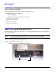
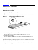
Figure 3-9 CPU 1 Slot Dust Cover
Step 6. Make sure the ZIF socket lock for the empty CPU 1 slot on the system board is unlocked by gently
trying to turn the 2.5 mm hex screwdriver counter clockwise. If the socket lock does not turn, the
socket is open and ready for the processor to be installed.
CAUTION When installing a processor and power pod module into the server blade,
make sure to hold the module on both sides. Failure to properly pick up the
module will break the module and render it unusable.
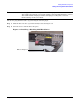
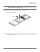
Step 7. Carefully install the assembled processor and power pod module into the empty CPU 1 slot on the
server blade system board. Line up the guide pins on the heat sink to the alignment holes in the
CPU slot to seat the CPU correctly. See Figure 3-10.
Figure 3-10 Alignment Holes in the CPU Slot
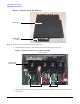
NOTE The CPU load order is CPU 0, then CPU 1. CPU 0 should be filled when the server
blade is purchased. See Figure 3-11 for slot locations.
Front of server
CPU 1 dust cover
ZIF socket lock
Front of server
Alignment holes