
Site Preparation Guide - HP Integrity BL60p Server Blade

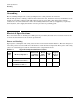

System Specifications
Environmental Specifications
Chapter 1
5
Environmental Specifications
This section provides the temperature and humidity requirements, noise emission, and air flow specifications
for the HP server.
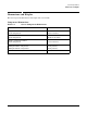
Temperature and Humidity
The recommended operating range is 20°C to 25°C (68°F to 77°F), and 40% – 55% relative humidity. Ambient
intake air temperature is often different from ambient room temperature; you should measure the operating
temperature and humidity directly in front of the cabinet cooling air intakes rather than just checking
ambient room conditions.
Operating Environment
The system is designed to run continuously and meet reliability goals in an ambient temperature of 5°C to
35°C (+40°F to +95°F) at sea level. The maximum allowable temperature is de-rated 1°C per 1,000 feet of
elevation above 5,000 feet above sea level up to 30°C (86°F) at 10,000 feet. For optimum reliability and
performance, the recommended operating range is 20°C to 25°C (68°F to 77°F), and 40% – 55% relative
humidity.
Environmental Temperature Sensor
The server includes internal sensors that monitor input air temperature and server operating temperatures.
The ambient air temperature is measured using a sensor placed on the system I/O board. Data from the
sensor is used to control the fan speed and also to initiate system overtemp shutdown.
Nonoperating Environment
The system is designed to withstand ambient temperatures between –40°C to 60°C (–40°F to 140°F) under
non-operating conditions.
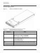
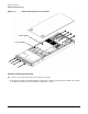
Cooling
CPU/Memory Cooling
The server incorporates front to back airflow across the HDD area and through the processor/memory area.
Four dual fan assemblies, mounted horizontally in the center of the chassis, pull air from the HDD area at the
front of the server, and push air through the processor and memory section.
Each dual fan assembly is controlled by smart fan control circuits that are embedded in the system I/O board.
The smart fan control circuit receives fan control input from the system fan controller in the I/O board, and
returns fan status information to the system fan controller. The smart fan circuit controls the power and the
pulse-width-modulated control signal to the fan and monitors the speed indicator back from each of the fans.
CAUTION For maximum cooling effects, ensure that the chassis ventilation holes are not blocked or
covered after installation.