
User Service Guide, Second Edition - HP Integrity BL60p Server Blade

Removing and Replacing Components
Removing and Replacing a Processor
Chapter 4
60
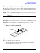
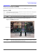
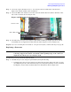
Figure 4-21 Power Pod and Processor Components
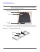
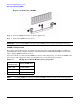
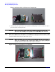
b. Assemble the power pod and processor together by sliding the processor board into the power
pod connector. Refer to Figure 4-22.
CAUTION Once the module is built, make sure to hold the module from both the
processor side and the power pod side to avoid breaking the connector.
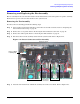
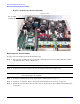
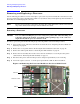
Step 2. Make sure the ZIF socket for the CPU you are installing is in the open position. Insert the 2.5 mm
hex end of the ACX-15 Torx screwdriver into the ZIF socket and gently try to rotate the socket 180º
counter clockwise. If it doesn’t turn, the socket is open.
CAUTION When installing a processor and powerpod module into the server blade,
make sure to hold the module on both sides. Failure to properly pick up the
module will break the module and render it unusable.
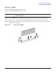
Figure 4-22 Power Pod and Processor Module