
User Service Guide, Second Edition - HP Integrity BL60p Server Blade


Removing and Replacing Components
Removing and Installing a Server Blade After a Server Blade Failure
Chapter 4
62
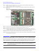
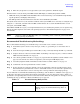
Step 5. Tighten the captive shoulder screws (1 - 4) on the processor heat sink in the order shown in
Figure 4-26 with the (ACX-15) Torx screwdriver.
Step 6. Tighten the captive screws (5 - 6) on the power pod with the (ACX-15) Torx screwdriver. Refer to
Figure 4-26.
Figure 4-26 Installing the Processor Module on the Server Blade Board
Step 7. Connect the power cable to the pod power connector on the processor power pod module.
Step 8. Install the fan assembly. Refer to “Replacing the Fan Assembly” on page 54.
Step 9. Install the airflow guide. If you are converting the blade to a one-processor system, make sure to
install the airflow blocker onto the airflow guide. Refer to “Replacing the Airflow Guide” on page 51.
Step 10. Install the access panel. Refer to “Replacing the Server Blade Access Panel” on page 47.
Step 11. Place the server blade back into the enclosure and power it up. Refer to “Replacing the Server Blade
into the Enclosure” on page 46.
Removing and Installing a Server Blade After a Server Blade Failure
The following procedure details how to remove a failed server blade, and replace it with a new server blade.
When a server blade fails, use the following components from the failed server blade (unless they caused the
failure): hard disk drives, memory DIMMs, and processors. Install these items in the new server blade.
CAUTION Electrostatic discharge can damage electronic components. Be sure you are properly grounded
before beginning any removal or installation procedure. See the “Safety Information” on
page 24 for more information.
Front of server
1
4
3
2
5
6